SDT-0060-00EN Situation: 17.06.2005 831.300 3
Instruction Manual Control and Switch Panel LT 500
3 Description and appropriate use
The job of the control and switch panel IT 500 is to control the electrical func-
tions in the living area of the motorhome and display various values such as
voltages and battery currents or water tank levels.
This system includes:
P
An Electrobloc, consisting of a charger module, the 12 V distribution and
the fuses for each circuit
P
Tank sensors for measuring the level in the water tanks
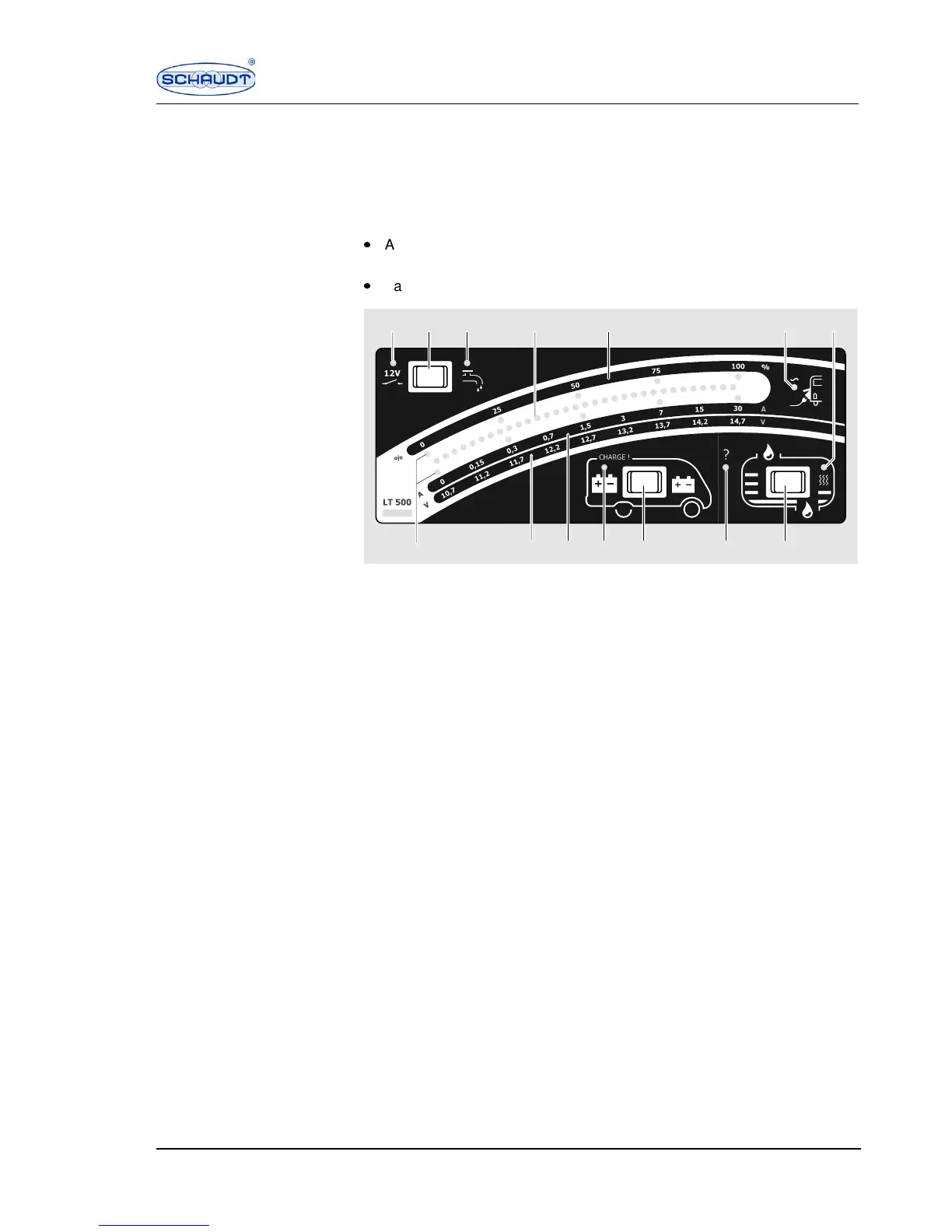
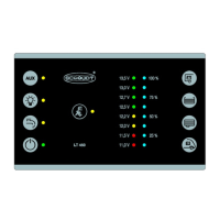
Fig. 1 Control and switch panel LT 500
1 12 V indicator lamp, green
2 12 V main switch/pump switch
3 Indicator lamp for pump power supply, yellow
4 Indicator LEDs: tank level, charging and discharge current, battery voltage
5 Percentage scale display: battery capacity/tank level "%"
6 230 V indicator lamp, yellow
7 Indicator lamp for waste water tank heater, yellow
8 Switch for tank level/waste water tank heater
9 "Unclear value" warning lamp, red "?"
10 Battery switch
11 Charge request "CHARGE !" warning lamp, red
12 Charging and discharge current scale "A"
13 Battery voltage scale "V"
14 Scale points
The 3 switches on the control and switch panel can be used for calling up var-
ious information and functions.
After letting go of the corresponding switch, the indicated values are still dis-
played for approx. 10 seconds.
SDT00277
1 2 3 4 75 6
891011121314