4 Situation: 17.06.2005 831.300 SDT-0060-00EN
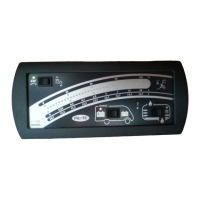
Instruction Manual Control and Switch Panel LT 500
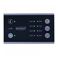
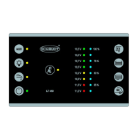
Values indicated on the
display
The indicated values are displayed in an illuminated band with 32 yellow indi-
cator LEDs in 16 levels. 5 scale points above and 5 below the illuminated
band indicate the range and make it easier to read the display. The right end
of the display shows the scale with illuminated units in percent (%), volts (V)
and amperes (A).
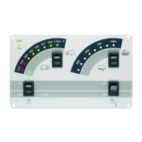
The brightness of the scale points and indicator LEDs is controlled depending
on the ambient light. The darker the ambient light, the darker the scale points
and indicator LEDs.
The following table shows possible indicated values.
The control and switch panel has bold-type numerical values.
4 Electrical data
5 Operation
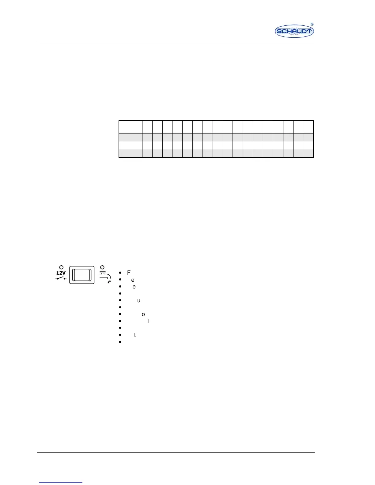
5.1 Switching the 12 V power supply for the living area
on and off
12 V main switch/pump
switch
The 12 V main switch/pump switch turns all consumers on and off.
Exceptions:
P
Frost protection valve
P
Heater
P
Step
P
Gas alarm/waste water valve
P
Circuits 4 and 5
P
Waste water tank heater
P
Pull-down bed
P
Awning light
P
Awning
P
Satellite antenna
P
Compressor or AES refrigerator
Press the left side of the switch briefly:
The 12 V power supply is switched on. The green 12 V indicator lamp
lights up.
Press the left side of the switch again briefly:
The 12 V power supply is switched off. The green 12 V indicator lamp does
not light up.
Indicator
LEDs
0 2 4 6 8 101214161820222426283032
Capacity % 0 6 13 19 25 31 38 44 50 56 63 69 75 81 88 94 100
Current A 0 0.1 0.15 0.2 0.3 0.45 0.7 1 1.5 2 3 4.5 7 10 15 20 30
Voltage V 10.7 11.0 11.2 11.5 11.7 12.0 12.2 12.5 12.7 13.0 13.2 13.5 13.7 14.0 14.2 14.5 14.7
Operating voltage 12 V (10–14.5 V), powered via Electrobloc