19
RSSI output
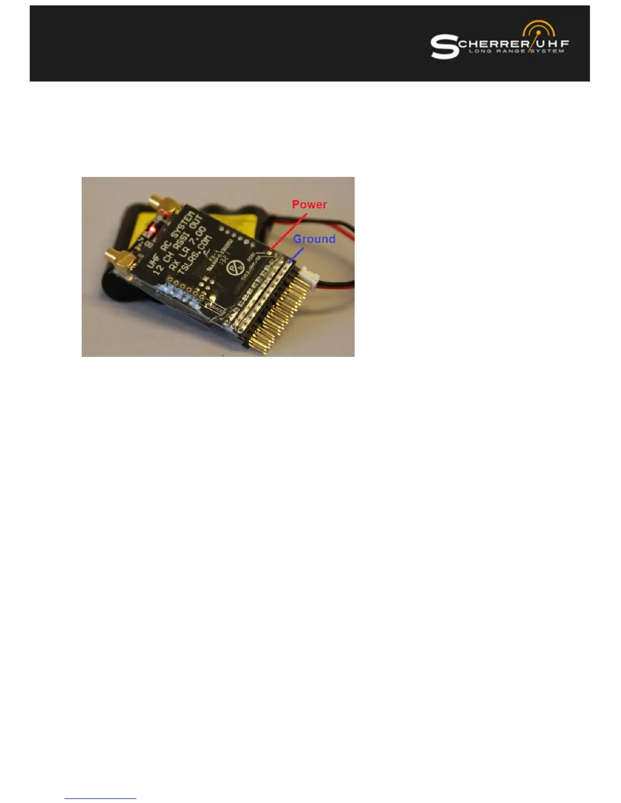
The little extra PAD over the CH12 connector is the RSSI output and you the bottom pin row for ground.
This is an analogue voltage that reveals how strong the signal is from the TX. Many OSD types can use this
voltage to display a calibrated 0-100% readout on the screen display. The Min and Max voltages are a little
bit different from RX to RX, so you must perform a new calibration if you swap a receiver in your system.
Connectors Servo
Look carefully at the connector pins and the PCB. The edge rows are all GROUND, the centre row are +5V
and all top pins are the servo channels out.
Serial Debug Output
The upgrade connector pin out
1 = GROUND (2, 3, 6 are not connected)
4 = Radio data (do not connect anything to this pin in flight mode)
5 = Debug data output
The debug out is a 3.3V serial signal, can be used for OSD or onboard flight recorders,
The data format is very simple, 9600 Baud 8N1.