4 Specification of Input and Output Data
Extension Board for MODBUS on SMARTCON Control Unit
DS-ENGLISH-MODBUS-V2.01-2019.05.15
4 Specification of Input and Output Data
General requirement: Depending on the Master it is possible that the Lowbyte (Bit 0 . . . 7) and the Highbyte
(Bit 8 . . . 15) are to be switched. Generally speaking, the mode of transmission (Big Endian / Little Endian) has
to be set in a way that ensures the correct transmission of the analogue information. Only after this has been
accomplished, the binary data can be transmitted.
4.1 Input Data Modules (Master to Slave Communication)
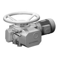
Input data can be handled with following Modbus functions:
Function:
06 (06 hex) Preset Single Register
Writes data to one single register in the
slave.
16 (10 hex) Preset Multiple Registers
Writes data to multiple consecutively
registers in the slave.
03 (03 hex) Read Holding Register
Reads back one single register from the
slave.
04 (04 hex) Read Input Register
Reads back one single register from the
slave.
23 (17 hex) Read/Write Multiple Registers
Writes data to multiple consecutively
registers in the slave and reads multiple
consecutively registers from the slave. If the
reading and writing addresses the same
registers, a read back of the written data is
performed. The write operation is performed
before the read operation.
4.1.1 Setpoint
Register number: 1, address 0000
Hex
Data format: 16bit, only the lowest 10 bits (0 . . . 1023) are in use.
Other bits are reserved for future use and have to be set to zero!
Value Function: Description:
0 (0
Hex
) 0 %
512 (200
Hex
) 50%
1023 (3ff
Hex
) 100%
6