92 • Schlage • ND-Series service manual
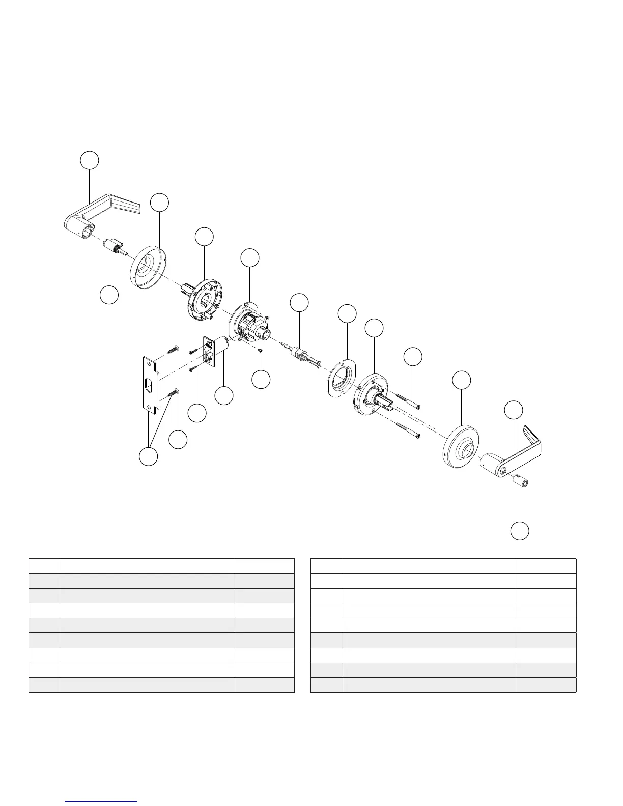
Trim assemblies
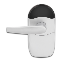
Corridor lock with Vandlgard
®
ND97
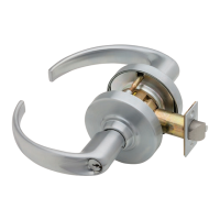
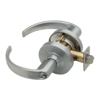
ND97PD (shown), ND97RD √, ND97GD √
A
M
V
Q
N
K
S
C
P
E
J
R
H
D
C
B
GG
Letter Description Part number
A Outside lever—open (cylinder) 03-231
B Inside lever—open (button) 03-233
C Rose 03-042
D Outside spring cage—standard N523-218
E Inside spring cage—standard N523-221
H Chassis 24088189*
J Anti-rotation plate N523-055
K Deadlatch 13-247
Letter Description Part number
M Strike assembly 10-025
N Latch screw C603-897
P Mounting screw N523-021
Q Strike screw C603-256
R Plunger—push button N123-086
S Cylinder—6-pin 23-065
V Push button N523-209
GG Adjustment plate screws N523-240
√ For RD (Full Size Interchangeable Core) and GD (SFIC) outside trim configurations, see page 98.
* Chassis part number is for reference only.
Designates new parts or assemblies.