For Sales and Support, Contact Walker EMD • www.walkeremd.com • Toll-free: (800) 876-4444 • Tel: (203) 426-7700 • Fax: (203) 426-7800
4
Operating instructions
Safety-monitoring module
EN
AES 2135
AES 2136
4
EN
8 Appendix
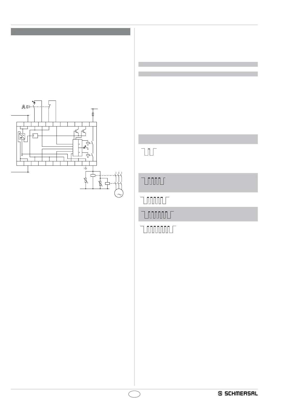
8.1 Wiring example
The application examples shown are suggestions. They however do not
release the user from carefully checking whether the switchgear and its
set-up are suitable for the individual application.
The wiring diagram is shown with guard doors closed and in a de-
energised condition. Inductive loads (e.g. contactors, relays, etc.) are
to be provided with suitable interference suppression circuitry. Do not
connect additional loads to terminal S..
AES 2135/2136
Guard door monitoring by means of a magnetic safety sensor (BNS)
AES 2135/2136
L1
K3
K4
3
N
M
BK
BU
BN
WH
24...230V AC/DC
24...230V AC/DC
A2
A2
X3 X4 X5 X6 X7 X8 14
13Y2Y1S22S21
100mA
max.
S14S13A1
A1
K2
P2
P1
K1
Legend
A S Non-contact safety sensor
8.2 Integral System Diagnostics (ISD)
The LED indication of the safety-monitoring modules shows the
different switching conditions and errors. The switching conditions are
explained in the following tables.
Tables switching condition indication
Diagnostic LED System condition
The LED is green. Enabling paths closed
LED ashes yellow (0.5 Hz) Enabling paths open
LED ashes yellow (2 Hz) Safety guard closed, however no release;
possible causes: incorrect operation
(only one contact actuated upon opening)
or voltage drop → perform start-up test
In case of error messages, the LED lights orange intermittently. During
these intermissions, the LED ashes one up to seven times with short
pulses.
Table error indications
Indication (orange)
LED
Error Cause
1 impulse
Inputs S1 Defective supply
voltage lead, defective
switch, erroneous
tting of the switch;
switch only partially
actuated for at least 5 s
4 impulses
Interference signals
at the inputs
(no safe evaluation
assured)
Too high capacitive or
inductive interference
at the switch's cables or
the supply voltage lead
5 impulses
One or both relays
did not close within
the monitoring time
Too low operating
voltage U
e
;
Defective relay
6 impulses
Relay not disabled
upon the actuation
of the switch
Relay contact welding
7 impulses
Dynamic monitoring
of both channels
(cross-monitoring)
failure
Fault in one channel;
internal data trans-
mission interrupted
* Partial actuation: position of the switch, in which only one contact was actuated.
Deleting the error message
The fault message is deleted once the fault has been rectied and after
the connected switch has been actuated to check the various functions.
 Loading...