Do you have a question about the schmersal AES 2135 and is the answer not in the manual?
Provides information for safe operation, mounting, set-up, and disassembly of the safety-monitoring module.
Specifies that operations must be carried out by trained specialist personnel authorized by the plant operator.
Details symbols for information, caution, and warnings, indicating potential failures or injuries.
Defines products are for safety-related functions in plants/machines; manufacturer ensures overall machinery safety.
User must observe safety instructions, country-specific standards, and accident prevention rules.
Inadequate use can lead to personal hazards or machinery damage; EN 1088 standard must be observed.
No liability for damages from defective mounting or non-compliance with manual; no liability for unauthorized parts.
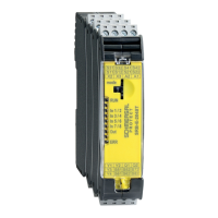
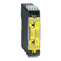
Lists product types and their options, specifically AES 2131.
Specifies that versions not listed in the order code follow standard version specifications.
Modules are for safety circuits, evaluating signals from switches and sensors for safety guards.
Provides detailed technical specifications, standards, voltage, current, and dimensions.
Details safety standards, performance level (PL), control category, and SIL.
Instructions for mounting the module onto standard DIN rails according to EN 60715.
Provides the physical dimensions of the device (H/W/D).
Electrical connection must only be carried out by authorised personnel in a de-energised condition.
Tests the safety function of the module, checking fitting and power cable integrity.
Module is maintenance-free with correct installation; recommends visual inspection and functional tests.
The safety monitoring module must be disassembled only in a de-energised condition.
Dispose of the module appropriately according to national prescriptions and legislations.
Shows suggested wiring diagrams for guard door monitoring with magnetic safety sensors.
Explains LED indications for switching conditions and error messages.
Certifies compliance with applicable European Directives for safety components.
Details the operating principle for both 'without start-up test' and 'with start-up test' configurations.
Describes how to connect safety switches or emergency-stop buttons at input S14/S22.
Explains bridging X3 and X4 for safety switches with two NC contacts, disabling short-circuit detection.
Details how to modify the output function of additional outputs by using a bridge between X5 and X6.
Explains how bridging X7/X8 extends the enable delay time for automatic start-up.
Describes enabling path 13-14 (NO contacts) and additional outputs Y1/Y2 for signalling.
The safety function must be tested, checking module fitting and power cable integrity.
Module is maintenance-free; recommends visual inspection and functional tests for safety.
The safety monitoring module must be disassembled in the de-energised condition only.
The safety monitoring module must be disposed of in an appropriate manner.
Application examples are suggestions and do not release the user from checking suitability for individual applications.
Explains LED indication of switching conditions and error messages.
Certifies that the safety components conform to applicable European Directives.
| Brand | schmersal |
|---|---|
| Model | AES 2135 |
| Category | Control Unit |
| Language | English |