Do you have a question about the schmersal SRB-E-204ST and is the answer not in the manual?
Provides information for mounting, set-up, and commissioning for safe operation and disassembly.
Operations must be carried out by trained specialist personnel authorised by the plant operator.
Details symbols used for information, hints, notes, cautions, and warnings.
Product must be used in accordance with listed versions and manufacturer-authorised applications.
User must observe instructions, country-specific standards, and safety regulations.
Improper use can lead to personal hazards or damage to machinery.
Manufacturer not liable for damages from defective mounting or unauthorized parts.
Lists the product types and available connection options like plug-in screw clamps.
Specifications for special versions not listed in the order code.
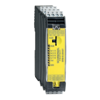
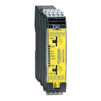
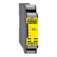
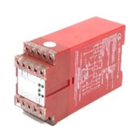
Modules for safety circuits in control cabinets; used for evaluating safety sensors.
Details electrical, mechanical, and ambient specifications like voltage, current, and temperature.
Information on derating for modules installed without spacing or with maximum output load.
Classification according to ISO 13849-1, IEC 61508, IEC 62061 standards.
Instructions for mounting the module onto standard DIN rails.
Specifies the physical dimensions of the device.
Electrical connection must be performed by authorised personnel in a de-energised condition.
Diagrams showing terminal assignments for SRB-E-204ST and SRB-E-204PE modules.
Details the function of each terminal and the meaning of LED indicators.
Table outlining adjustable applications based on rotary knob position.
Procedure for changing the device's setting or application using the rotary switch.
Explains the meaning of LED indications for different operating states and errors.
Lists error causes and corresponding LED flash codes for troubleshooting.
Lists applications for 1 or 2-channel safe evaluation for protective equipment.
Illustrates a dual-channel control for a guard door monitor with position switches.
Details monitored start and reset without monitoring/autostart configurations.
Describes using feedback circuits for increased capacity or contact number.
Explains using inputs X2 and X3 for cascading multiple SRB-E-204PE modules.
Shows single and dual channel signal processing configurations for sensors.
Module features IP54 protection for switch cabinet installation; delivered ready for operation.
Tests safety function, cable integrity, enclosure, and connected sensor technology.
Recommended procedure for handling faults, including identifying and rectifying them.
A report format for documenting device settings, to be completed by the customer.
Recommends regular visual inspection and functional tests for the module.
The module must be disassembled only when it is de-energised.
The module must be disposed of according to national prescriptions and legislations.
Information on the use of safety outputs Q1, Q2 and additional safety functions.
| Product name | SRB-E-204ST |
|---|---|
| Category | Control Unit |
| Supply voltage | 24 V DC |
| Safety Integrity Level | SIL 3 |
| Performance Level | PL e |
| Mission Time | 20 years |
| Temperature Range | -25°C to +55°C |
| Protection Class | IP20 |
| Housing material | Plastic |
| Connection type | Screw terminals |
| Ambient temperature | -25°C to +55°C |
| Current Consumption | 100 mA |
| Input | 2-channel |
| Switching distance | Not applicable |