9
SRB-E-204ST / SRB-E-204PE
Operating instructions
Safety-monitoring module
EN
7.3 Start configuration SRB-E-204ST
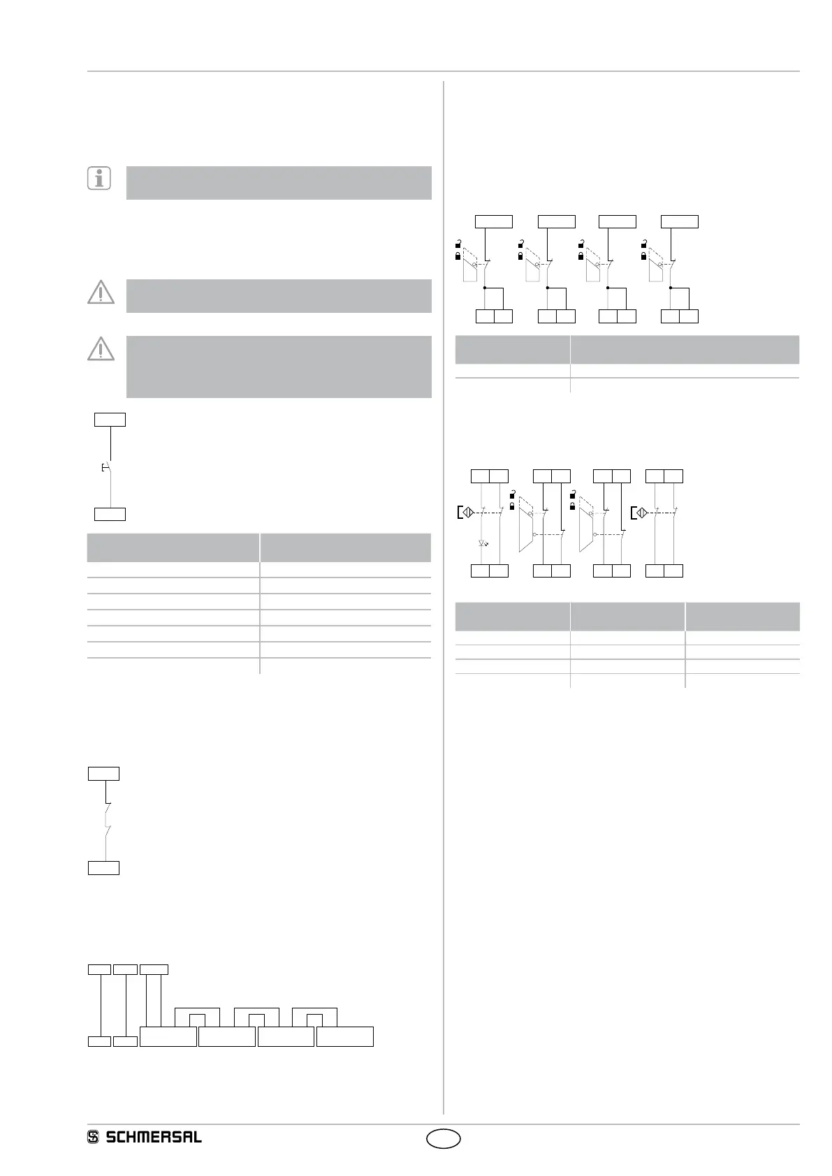
7.3.1 Monitored start
• Manual start or activation of the module occurs when the button is
released.
Monitoring of max. actuation time 0.03 sec. … 3 sec.
If the time is exceeded, the module cannot be started!
7.3.2 Reset without monitoring / autostart
• The manual start or the activation of the module occurs when the
button is pressed (not when it is released!).
• With autostart, X2 must be bridged to +24 VDC
Not admitted without additional measure due to the risk of
gaining access by stepping behind!
Within the meaning of IEC/EN 60204-1 paragraph 9.2.5.4.2
the operating mode "automatic start" is only restrictedly
admissible. In particular, any inadvertent restart of the
machine must be prevented by other suitable measures.
X2
+24 VDC
J
Reset button (detection
of the trailing edge)
Reset without monitoring /
autostart
Rotary knob position 1 Rotary knob position 6
Rotary knob position 2 Rotary knob position 7
Rotary knob position 3 Rotary knob position 8
Rotary knob position 4 Rotary knob position 9
Rotary knob position 5 Rotary knob position 10
Rotary knob position 11 Rotary knob position 12
Rotary knob position 13 Rotary knob position 14
7.4 Feedback circuit SRB-E-204ST
• Suitable for increase in capacity or number of contacts by means of
contactors or relays with positive-guided contacts. If the feedback
circuit is not required, establish a bridge.
X3
+24 VDC
K
B
K
A
7.5 Cascading SRB-E-204PE
• Safety inputs X2 and X3 can be used for cascading of several
SRB-E-204PE modules.
• Without cascading, inputs X2 and X3 must be bridged to +24 VDC.
X2 X3
+24 VDC+24 VDC
SRB-E204PE (1)
+24 VDC
X2 X3 Q1 Q2
SRB-E204PE (2)
X2 X3 Q1 Q2
SRB-E204PE (3)
X2 X3 Q1 Q2
SRB-E204PE (x)
7.6 Sensor configuration
• Different protective equipment can be monitored.
See examples as follows
• Sequence of protective equipment can be chosen freely
• Unrequired inputs S12, S22, S32, S42, S52, S62, S72, S82 must be
bridged to outputs S11, S21, S31, S41, S51, S61.
Single channel signal processing (Sensor 1 – 4)
S12 S22 S32 S42
S11/+24V S31/+24V
S52 S62 S72 S82
S51/+24V S61/+24V
Rotary knob
position
Function
(SRB-E-204ST)
4 Reset button (detection of the trailing edge)
10 Reset without monitoring / autostart
Dual channel signal processing NC / NC (Sensor 1 – 4)
With cross-wire monitoring
(Category 4 – PL e to ISO 13849-1 possible)
S12 S22
S11 S21
S32 S42
S31 S41
S52 S62
S51 S61
S72 S82
S51 S61
Rotary knob
position
Cross-wire
monitoring
Synchronisation
1 Yes Yes
2 Yes No
7 (SRB-E-204ST) Yes Yes
8 (SRB-E-204ST) Yes No