3
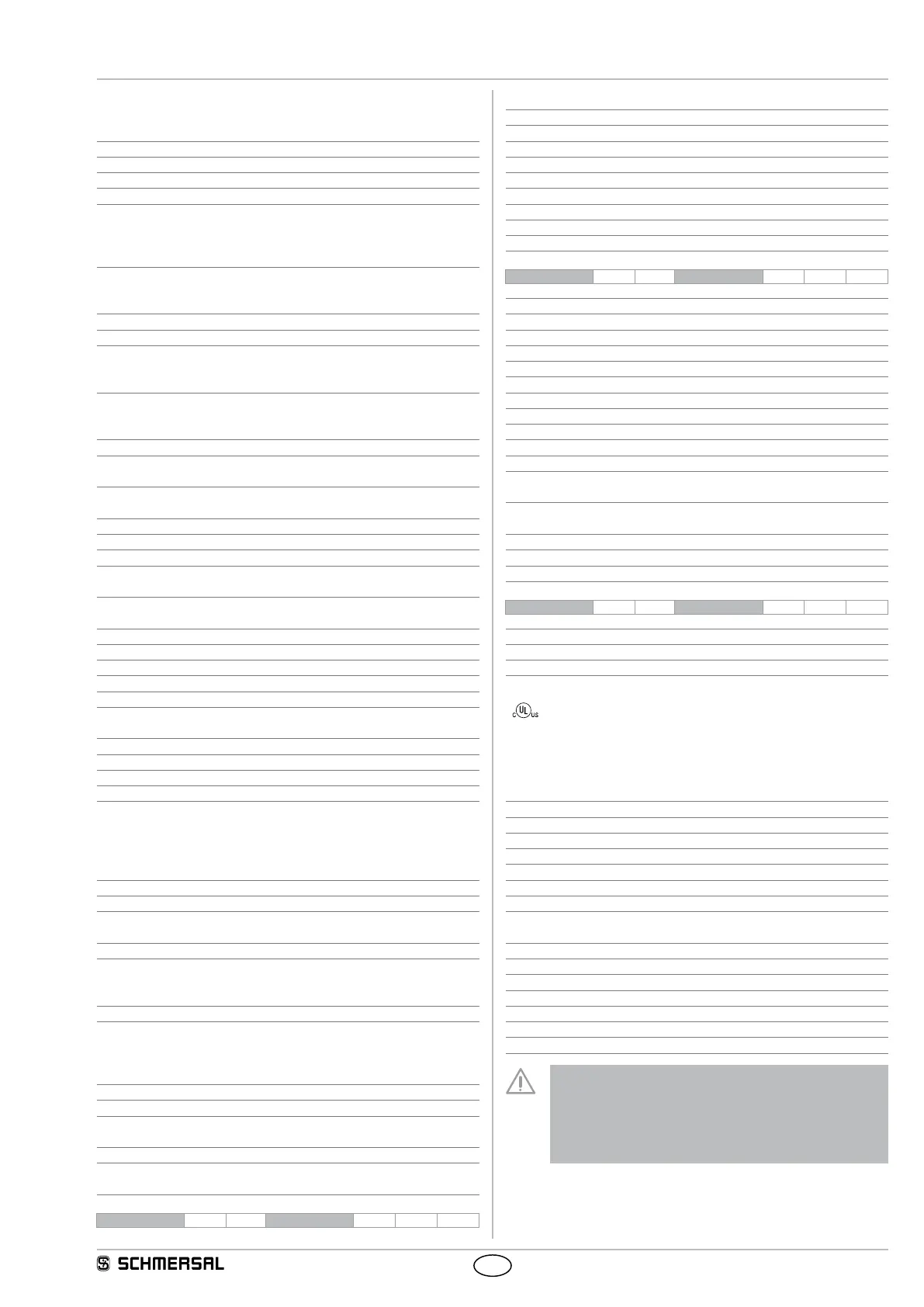
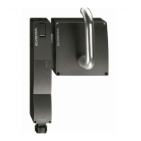
AZM201
Operating instructions
Solenoid interlock
EN
2.5 Technical data
Standards: IEC 60947-5-1, IEC 60947-5-3, ISO 14119,
ISO 13849-1, IEC 61508, IEC 62061
Enclosure: glass-fibre reinforced thermoplastic, self-extinguishing
Working principle: RFID
Frequency band: 125 kHz
Transmitter output: max. -6 dBm
Coding level according to ISO 14119:
- I1-version: high
- I2-version: high
- Standard coding version: low
Reaction time:
- Actuator: ≤ 100 ms
- Inputs: ≤ 0.5 ms
Duration of risk: < 200 ms
Time to readiness: < 4,000 ms
Series-wiring: Unlimited number of components,
please observe external cable protection,
max. 31 components in case of serial diagnostics
Cable length: max. 200 m
(cable length and cable section alter the voltage
drop depending on the output current)
Mechanical data
Termination: Screw terminals or cage clamps,
Connector plug M12
Cable section: min. 0.25 mm², max. 1.5 mm²
(including conductor ferrules)
Cable entry: M20
Tightening torque for the cover screws: 0.7 ... 1 Nm (Torx T10)
Latching force: 30 N
Holding force F
max
: 2,600 N (1,300 N when used with the
AZ/AZM201-B30 actuator, for indoor use)
Holding force F
Zh
: 2,000 N (1,000 N when used with the
AZ/AZM201-B30 actuator, for indoor use)
Actuating speed: ≤ 0.2 m/s
Mechanical life: ≥ 1,000,000 operations
Ambient conditions
Ambient temperature: −25 °C ... +60 °C
Storage and transport temperature: −25 °C ... +85 °C
Relative humidity: max. 93 %,
non condensing, non icing
Protection class: IP66, IP67 to IEC 60529
Protection class: III
Resistance to shock: 30 g / 11 ms
Resistance to vibration: 10 ... 150 Hz, amplitude 0.35 mm
Insulation values to IEC 60664-1:
- Rated insulation voltage U
i
: 32 VDC
- Rated impulse withstand voltage U
imp
: 0.8 kV
- Over-voltage category: III
- Degree of pollution: 3
Switching frequency: 1 Hz
Electrical data
Operating voltage U
B
: 24 VDC −15% / +10%
(stabilised PELV power supply)
Power consumption device: ≤ 0.05 A
Operating current device with magnet switched on:
- Averaged: < 0.2 A
- Peak current: < 0.7 A / 100 ms
Required rated short-circuit current: 100 A
External device fuse rating:
- Screw terminals or cage clamps: ≤ 4 A when used
in accordance with UL
508;
- Connector plug M12 or M23: ≤ 2 A
Electrical data - Safety inputs
Safety inputs: X1 and X2
Switching thresholds: −3 V ... 5 V (Low)
15 V ... 30 V (High)
Power consumption per input: typically 2 mA / 24 V
Accepted test pulse duration on input signal: ≤ 1.0 ms
- With test pulse interval of: ≥ 100 ms
Classification: ZVEI CB24I
Countersink: C1 Source: C1 C2 C3
Electrical data - Safety outputs
Safety outputs: Y1 and Y2
Switching elements: OSSD, p-type, short-circuit proof
Utilisation category: DC-13: U
e
/I
e
: 24 VDC / 0.25 A
Rated operating current I
e
: each max. 0.25 A
Leakage current I
r
: ≤ 0.5 mA
Voltage drop U
d
: ≤ 4 V
Cross-wire monitoring by device: Yes
Test pulse duration: < 0.5 ms
Test pulse interval: 1,000 ms
Classification: ZVEI CB24I
Source: C2 Countersink: C1 C2
Electrical data - Diagnostic output
Diagnostic output: OUT
Switching element: p-type, short-circuit proof
Utilisation category: DC-13: U
e
/I
e
: 24 VDC / 0.05 A
Rated operating current l
e
: max. depending 0.05 A
Voltage drop U
d
: ≤ 4 V
Serial diagnostic SD
Operating current: 0.15 A
Wiring capacitance: max. 50 nF
Electrical data - Magnet control
Solenoid input: IN
Switching thresholds: −3 V ... 5 V (Low)
15 V ... 30 V (High)
Power consumption: typical 10 mA / 24 V,
dynamic 20 mA
Magnet switch-on time ED: 100 %
Accepted test pulse duration on input signal: ≤ 5.0 ms
- With test pulse interval of: ≥ 40 ms
Classification: ZVEI CB24I
Countersink: C0 Source: C1 C2 C3
LED status display
green LED: Supply voltage
yellow LED: Device condition
red LED: Fault
Use isolated power supply only.
For use in NFPA 79 Applications only.
Adapters providing field wiring means are available from
the manufacturer. Refer to manufacturers information.
2.6 Safety classification
- of the interlocking function
Standards: ISO 13849-1, IEC 61508, IEC 62061
PL: e
Control Category: 4
PFH value: 1.9 x 10
-9
/ h
PFD: 1.6 x 10
-4
SIL: suitable for SIL 3 applications
Service life: 20 years
- of the guard locking function
Standards: ISO 13849-1, IEC 61508, IEC 62061
PL: d
Control Category: 2
PFH: 1.0 x 10
-8
/ h
PFD: 8.9 x 10
-4
SIL: suitable for SIL 2 applications
Service life: 20 years
The safety consideration of the guard locking function
only applies for standard devices with monitored solenoid
interlock AZM201Z-…-1P2PW-… (see Ordering code).
A safety assessment of the guard locking function for
devices with serial diagnostics "SD2P" is not allowed due to
the non-safe locking/unlocking signal from the SD Gateway