8
Operating instructions
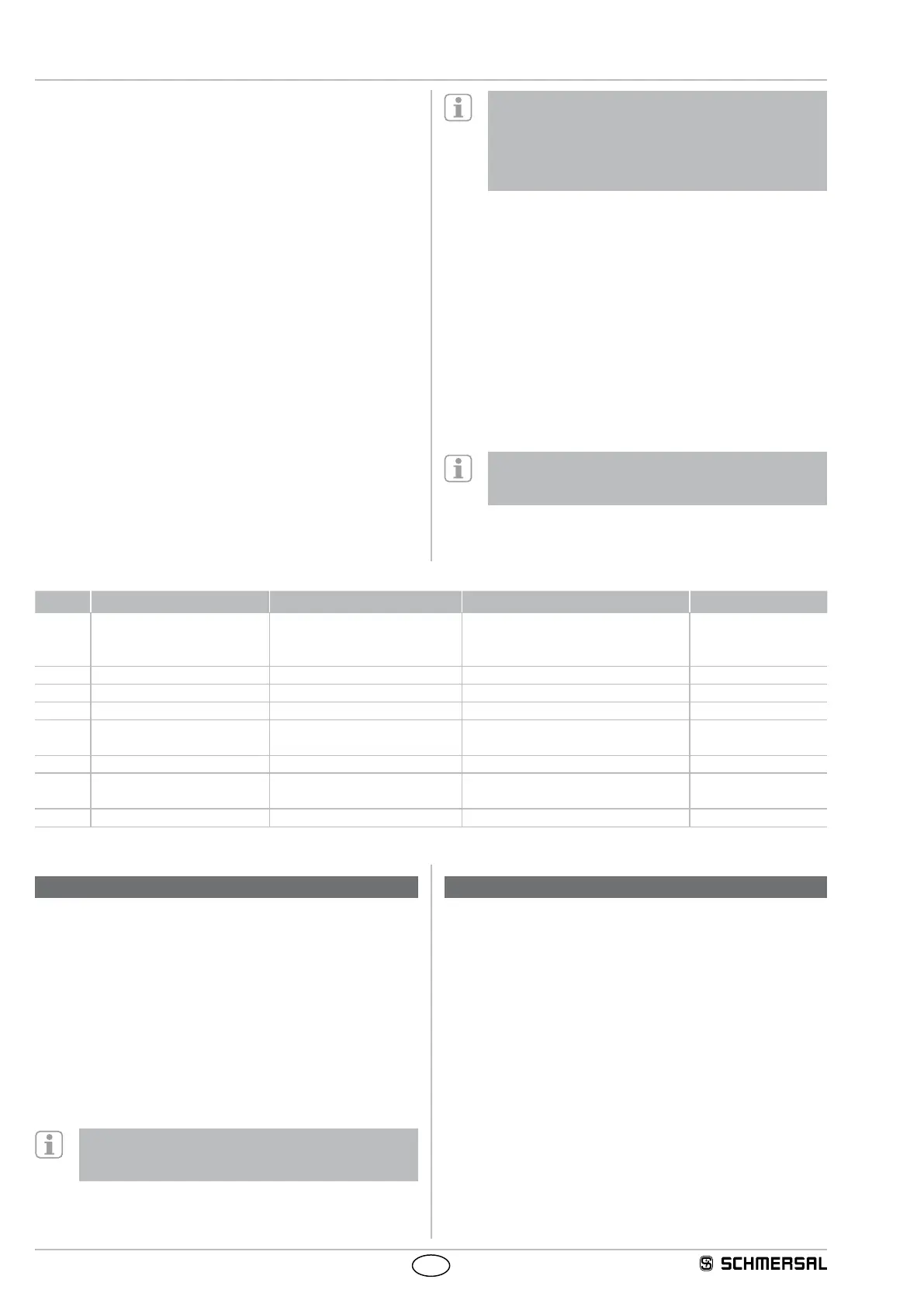
Solenoid interlock
AZM201
EN
Automatic, electronic locking takes place if more than one
fault is detected at the safety outputs or a cross circuit is
detected between Y1 and Y2. This means that normal fault
acknowledgement is no longer possible. To reset this type of
interlocking, the solenoid interlock must be isolated from the
power supply after elimination of the error causes.
Error warning
A fault has occurred, which causes the safety outputs to be disabled
after 30 minutes. The safety outputs initially remain enabled.
This enables the shutdown of the process in a controlled manner.
An error warning is deleted when the cause of error is eliminated.
Diagnostic error (warning)
If an error (warning) is signalled in the response byte, detailed fault
information can be read out.
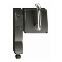
Accessories for the series-wiring
To provide for a comfortable wiring and series-wiring of SD
components, the connectors and the SD-2V-F-SK SD junction boxes
(variant for the field in closed enclosure) and SD-2V-S-SK
(variant for DIN rail mounting in the control cabinet) are available.
On wiring SD devices, please pay attention to the voltage
drop on the cables and the current carrying capacity of the
individual components.
Table 3: I/O data and diagnostic data
Bit n° Request byte Response byte Diagnostic error warning Diagnostic error
Bit 0: Magnet in, irrespective of
power to lock or power to
unlock principle
Safety output activated Error output Y1 Error output Y1
Bit 1: --- Actuator detected Error output Y2 Error output Y2
Bit 2: --- Actuator detected and locked Cross-wire short Cross-wire short
Bit 3: --- --- Temperature too high Temperature too high
Bit 4: --- Input condition X1 and X2 --- incorrect or defective
actuator
Bit 5: --- Guard door detected Internal device error Internal device error
Bit 6: --- Error warning
1)
Communication error between the field
bus Gateway and the safety switchgear
---
Bit 7: Error reset Error (enabling path switched off) Operating voltage too low ---
1)
after 30 min -> fault
The described condition is reached, when Bit = 1
6.3 Solenoid interlock with serial diagnostic function SD
Solenoid interlocks with serial diagnostic cable have a serial input and
output cable instead of the conventional diagnostic output. If solenoid
interlocks are wired in series, the diagnostic data is transmitted through
the series-wiring of the inputs and outputs.
Max. 31 solenoid interlocks can be wired in series. For the evaluation of
the serial diagnostics line either the PROFIBUS-Gateway SD-I-DP-V0-2
or the Universal-Gateway SD-I-U-... are used. This serial diagnostic
interface is integrated as a slave in an existing field bus system. In this
way, the diagnostic signals can be evaluated by means of a PLC.
The response data and the diagnostic data are automatically and
permanently written in an input byte of the PLC for each solenoid
interlock in the series-wired chain. The request data for each solenoid
interlock is transmitted to the component through an output byte of the
PLC. In case of a communication error between the field bus gateway
and the solenoid interlock, the switching condition of the solenoid
interlock is maintained.
Error
A fault has occurred, which causes the safety outputs to be disabled.
The fault is reset, when the cause is eliminated and bit 7 of the request
byte changes from 1 to 0 or the safety guard is opened. Faults at the
safety outputs are only deleted upon the next release, as the fault
rectification cannot be detected sooner.
7. Set-up and maintenance
7.1 Functional testing
The safety function of the safety components must be tested.
The following conditions must be previously checked and met:
1. Fitting of the solenoid interlock and the actuator
2. Check the integrity of the cable entry and connections
3. Check the switch enclosure for damage
7.2 Maintenance
We recommend a regular visual inspection and
functional test, including the following steps:
1. Check for tight installation of the actuator and the switch
2. Remove particles of dust and soiling
3. Check cable entry and connections
Adequate measures must be taken to ensure protection
against tampering either to prevent tampering of the safety
guard, for instance by means of replacement actuators.
Damaged or defective components must be replaced.
8. Disassembly and disposal
8.1 Disassembly
The safety switchgear must be disassembled in a de-energised
condition only.
8.2 Disposal
The safety switchgear must be disposed of in an appropriate manner in
accordance with the national prescriptions and legislations.