5
AZM201
Operating instructions
Solenoid interlock
EN
4. Electrical connection
4.1 General information for electrical connection
The electrical connection may only be carried out by
authorised personnel in a de-energised condition.
The power supply for the solenoid interlock must provide protection
against permanent overvoltage. To that effect, stabilised PELV supply
units must be used. The safety outputs can be directly integrated in the
safety circuit of the control system. For applications up to
PL e / control category 4 in accordance with ISO 13849-1, the safety
outputs of the solenoid interlock(s) must be connected to a safety-
monitoring module of the same control category (refer to wiring
examples). Inductive loads (e.g. contactors, relays, etc.) are to be
provided with suitable interference suppression circuitry.
Requirements for the connected safety-monitoring module:
• Dual-channel safety input, suitable for 2 p-type semi-conductor
outputs
Configuration of the safety controller
If the safety switchgear is connected to electronic safety-
monitoring modules, we recommend that you set a
discrepancy time of 100 ms. The safety inputs of the safety-
monitoring module must be able to blank a test impulse of
approx. 1 ms. The safety-monitoring module does not need to
have a cross-wire short monitoring function, if necessary, the
cross-wire short monitoring function must be disabled.
Information for the selection of suitable safety-monitoring
modules can be found in the Schmersal catalogues or in the
online catalogue on the Internet: www.schmersal.net.
If the safety component is wired to relays or to non-safety relevant
control components, a new risk analysis must be carried out.
Cable
The cable entry is realised by a metric M20 gland. This gland must be
measured by the user so that it is suitable for the cable used. A cable
gland with strain relief and suitable IP protection class must be used.
The maximum cable length is 200 m (for ST2 M12 connectors approx.
20 m depending on the cable section used for an operating current
of 0.5 A). The maximum cable section is 1.5 mm², incl. conductuor
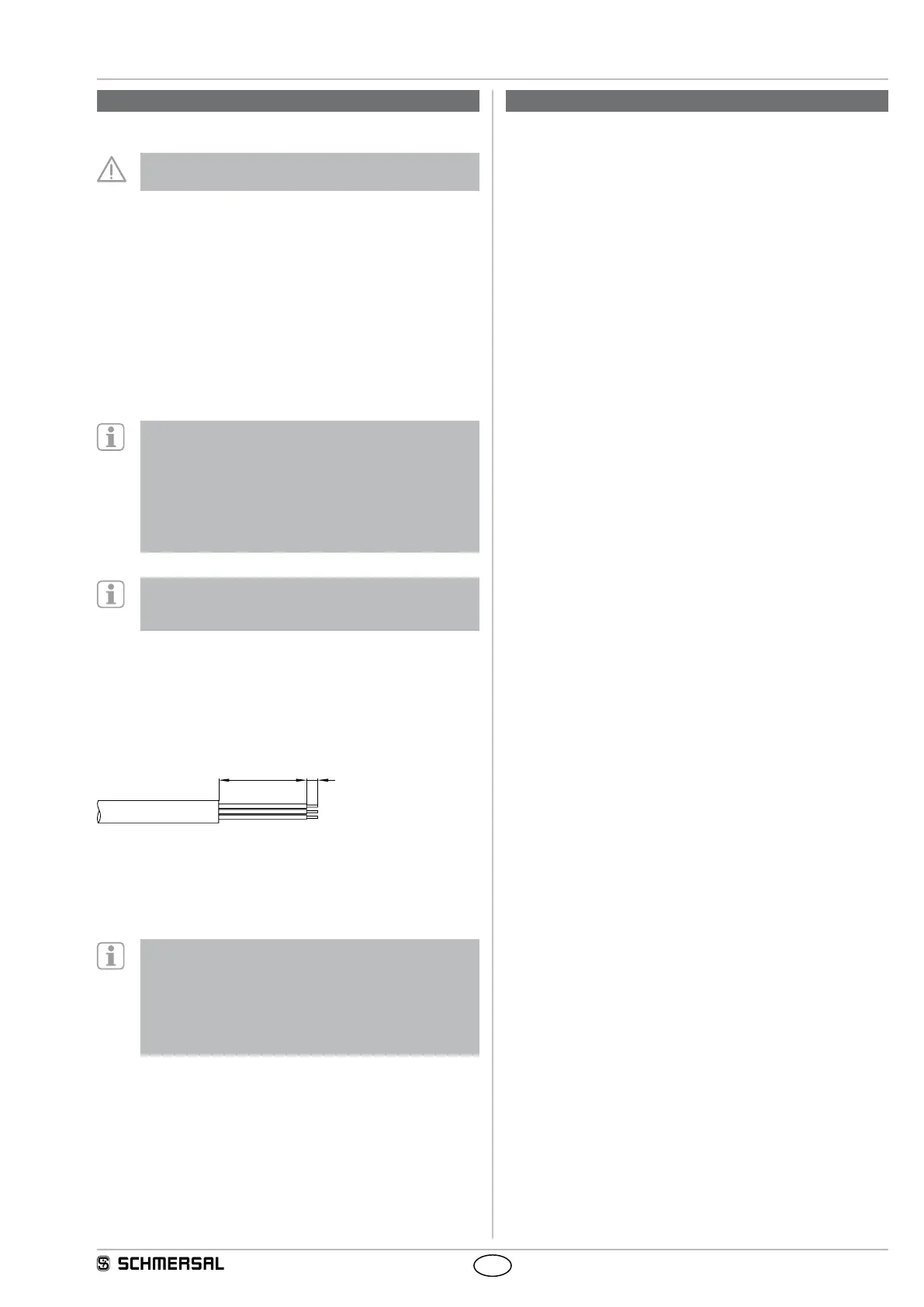
ferrules. Prior to the connection, the cable must be stripped by
40+5 mm and insulated by 5 mm. The fitted 24V, X1, X2 bridge is
included in the delivery of …-1P2PW and …-SD2P.
Accessories for the series-wiring
For convenient wiring and series-wiring of SD components,
the SD junction boxes PFB-SD-4M12-SD (variant for the
field) and PDM-SD-4CC-SD (variant for control cabinet on
carrier rail) are available along with additional comprehensive
accessories. Detailed information is available on the Internet,
www.schmersal.net.
5. Operating principles and coding
5.1 Magnet control
In the power to unlock version of the AZM201, the solenoid interlock is
unlocked when the IN signal (= 24V) is set. In the power to lock version
of the AZM201, the solenoid interlock is locked when the IN signal
(= 24 V) is set.
5.2 Mode of operation of the safety outputs
In the standard AZM201 variant, the unlocking of the solenoid interlock
causes the safety outputs to be disabled. The unlocked safety guard
can be relocked as long as the actuator is inserted in the AZM201
solenoid interlock; in that case, the safety outputs are re-enabled.
The safety guard must not be opened.
In the B-variant AZM201B, the opening of the safety guard causes the
safety outputs to be disabled.
5.3 Actuator teaching / actuator detection
Solenoid interlocks with standard coding are ready to use upon delivery.
Individually coded solenoid interlocks and actuators will require the
following "teach-in" procedure:
1. Switch the solenoid interlock's voltage supply off and back on.
2. Introduce the actuator in the detection range. The teach-in procedure
is signalled at the solenoid interlock, green LED off, red LED on,
yellow LED flashes (1 Hz).
3. After 10 seconds, brief yellow cyclic flashes (5 Hz) request the
switch-off of the operating voltage of the solenoid interlock. (If the
voltage is not switched off within 5 minutes, the solenoid interlock
cancels the "teach-in" procedure and signals a false actuator by 5 red
flashes).
4. After the operating voltage is switched back on, the actuator must
be detected once more in order to activate the taught actuator code.
In this way, the activated code is definitively saved!
For ordering suffix -I1, the executed allocation of safety interlock
and actuator is irreversible.
For ordering suffix -I2, the "teach-in" procedure for a new actuator can
be repeated an unlimited number of times. When a new actuator is
taught, the code, which was applicable until that moment, becomes
invalid. Subsequent to that, an enabling inhibit will be active for ten
minutes, thus providing for an increased protection against tampering.
The green LED will flash until the expiration of the time of the enabling
inhibit and the detection of the new actuator. In case of power failure
during the lapse of time, the 10-minutes tampering protection time will
restart.