EasyManua.ls Logo

schmersal RSS 36-I2-D-ST - User Manual

schmersal RSS 36-I2-D-ST
23 pages
Print Icon
To Next Page IconTo Next Page
Loading...
INSTRUCTIONS FOR OPERATION AND
ASSEMBLY
ELECTRONIC SAFETY-SENSOR RSS 36-
I2-D-ST
Table of Contents
1 About this document
1.1 Function
1.2 Target group of the operating instructions: authorised qualified personnel
1.3 Explanation of the symbols used
1.4 Appropriate use
1.5 General safety instructions
2 Product description
2.1 Ordering code
2.2 Special versions
2.3 Purpose
2.4 Warning about misuse
2.5 Exclusion of liability
3 Technical Data
4 Mounting
4.1 General mounting instructions
4.2 Dimensions
4.3 Accessories
4.4 Switch distance
4.5 Adjustment
5 Electrical connection
5.1 General information for electrical connection
5.2 Serial diagnostic -SD
5.3 Wiring examples for series-wiring
5.4 Wiring configuration and connector accessories
6 Actuator coding
7 Working principle and diagnostic function
7.1 Mode of operation of the safety outputs
7.2 Diagnostic-LEDs
7.3 Operating principle of the electronic diagnostic output
7.4 Safety-sensors with serial diagnostic function
8 Set-up and maintenance
9 Disassembly and disposal
9.1 Disassembly
9.2 Disposal
1 About this document
Question and Answer IconNeed help?

Do you have a question about the schmersal RSS 36-I2-D-ST and is the answer not in the manual?

Summary

About This Document

General Safety Instructions

User must observe safety instructions, country-specific standards, and safety regulations.

Product Description

Ordering Code Explained

Details the product type description and its various coding options.

Technical Data

Safety Classification Details

Details safety standards, performance level, category, PFH, PFD, SIL, and mission time.

Mounting

General Mounting Instructions

Provides guidelines for mounting safety sensors and actuators, including standards and interference avoidance.

Switch Distance

Details the assured switching distances (Sao, Sar) and typical values according to IEC 60947-5-3.

Adjustment

Explains how to adjust the sensor and actuator, including LED indicators for detection status.

Electrical Connection

General Information for Electrical Connection

Covers integration into safety circuits, cable fuse protection, and requirements for monitoring modules.

Working Principle and Diagnostic Function

Mode of Operation of Safety Outputs

Explains how safety outputs are integrated and disabled when a safety guard is opened.

Set-up and Maintenance

Maintenance and Testing

Recommends visual inspection and functional tests for safe operation and maintenance-free functionality.

Overview

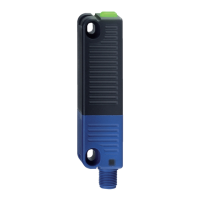
This document describes the Schmersal RSS 36-12-D-ST Electronic Safety-Sensor, a non-contact, electronic safety sensor designed for applications in safety circuits. It is used for monitoring the position of movable safety guards, such as hinged, sliding, or removable safety guards, by means of a coded electronic actuator. The safety function involves safely switching off the safety outputs when the safety guard is opened and maintaining this switched-off condition as long as the guard remains open.

Function Description:

The RSS 36-12-D-ST is classified according to ISO 14119 as a type 4 interlocking device. Designs with individual coding are considered highly coded. The sensor operates on the RFID working principle, utilizing a frequency band of 125 kHz. It can be used as a door end stop for guards up to 5 kg at 0.25 m/s. The diagnostic output can function as a conventional output or as a "serial output" with input and output channels. Series-wiring is supported, with the number of devices limited by cable drops and external fuse protection. Up to 31 device variants with serial diagnostics can be wired in series. The safety outputs can be integrated into the safety circuit of a control system, suitable for applications up to PL e / category 4 according to EN ISO 13849-1. The sensors cyclically switch off the safety output for self-testing, and the safety-monitoring module must tolerate these switch-off times.

Important Technical Specifications:

General Data:

  • Standards: EN ISO 13849-1, EN IEC 60947-5-3, EN IEC 61508
  • Performance Level: up to e
  • Category: 4
  • PFH value: 2.70 x 10^-10 /h
  • PFD value: 2.10 x 10^-5
  • Safety Integrity Level (SIL): 3
  • Mission time: 20 Year(s)
  • Housing construction form: Block, not flush
  • Enclosure material: Plastic, glass-fibre reinforced thermoplastic, self-extinguishing
  • Gross weight: 80 g
  • Time to readiness, maximum: 2,000 ms
  • Reaction time, maximum: 100 ms
  • Duration of risk, maximum: 200 ms
  • Reaction time, switching off safety outputs via actuator, maximum: 100 ms
  • Reaction time, switching off safety outputs via safety inputs, maximum: 0.5 ms
  • Features: Diagnostic output, Short circuit detection, Cross-circuit detection, Series-wiring, Safety functions, Cascadable, Integral system diagnostics, status.
  • Number of LEDs: 3
  • Number of semi-conductor outputs with signaling function: 1
  • Number of fail-safe digital outputs: 2

Mechanical Data:

  • Actuating panels/Active area: lateral
  • Hysteresis (Switching distance), maximum: 2 mm
  • Repeat accuracy R: 0.5 mm
  • Axial offset: Maximum height misalignment (x) of sensor and actuator of 8 mm; axial misalignment (y) is max. ± 18 mm.
  • Minimum clearance between two sensor systems: 100 mm.
  • Type of fixing screws: 2x M4 (cylinder head screws with washers DIN 125A / form A)
  • Tightening torque of fixing screws: minimum 2.2 Nm, maximum 2.5 Nm
  • Assured switching distance "ON" Sao: 10 mm
  • Assured switching distance "OFF" Sar: 20 mm
  • Switch distance, typical: 12 mm
  • Termination: Connector M12, 8-pole (or 5-pole for ST5 variants)
  • Dimensions: Length 22 mm, Width 106.3 mm, Height 25 mm

Ambient Conditions:

  • Degree of protection: IP65, IP67, IP69
  • Ambient temperature: minimum -25 °C, maximum +70 °C
  • Storage and transport temperature: minimum -25 °C, maximum +85 °C
  • Relative humidity, maximum: 93% (non-condensing, non-icing)
  • Resistance to vibrations: 10 ... 55 Hz, amplitude 1 mm
  • Resistance to shock: 30 g / 11 ms
  • Protection class: III
  • Permissible installation altitude above sea level, maximum: 2,000 m

Electrical Data:

  • Operating voltage: 24 VDC -15% / +10% (stabilised PELV power supply)
  • Operating current, minimum: 0.5 mA
  • No-load supply current Io, maximum: 35 mA
  • Rated operating voltage: 24 VDC
  • Operating current: 600 mA
  • Required rated short-circuit current: 100 A
  • Switching frequency, maximum: 1 Hz
  • Safety inputs (X1 and X2): Current consumption 5 mA, Test pulse duration max 1 ms, Test pulse interval min 100 ms.
  • Safety outputs (Y1 and Y2): Rated operating current 250 mA, Output current (fail-safe output) max 0.25 A, short-circuit proof, p-type, Voltage drop Ud max 1 V, Leakage current I max 0.5 mA.
  • Diagnostic outputs (OUT): short-circuit proof, p-type, Voltage drop Ud max 2 V, Current, Utilisation category DC-12/DC-13 0.05 A.
  • EMC rating: IEC 61000-6-4, IEC 60947-3

Usage Features:

  • Ordering Code: The ordering code RSS 36 (1)-(2)-(3)-(4) allows for customization:
    • (1) Coding: "without" (Standard), "I1" (Individual), "I2" (Individual, re-teaching enabled).
    • (2) Diagnostic Function: "without" (only on request for ST5), "D" (With diagnostic output), "SD" (with serial diagnostics, only for ST).
    • (3) Latching: "without" or "R" (with latching, approx. 18 N force).
    • (4) Connector: "ST" (M12, 8-pole) or "ST5" (M12, 5-pole).
  • Actuator Coding: Safety sensors with standard coding are ready to use. Individually coded sensors require a "teach-in" procedure: energize sensor, introduce actuator, wait 10 seconds for yellow flashes (3 Hz), switch off/on operating voltage, re-detect actuator to save code. For "I1" versions, this is irreversible. For "I2" versions, re-teaching is possible, invalidating the old code and activating a 10-minute tampering protection time.
  • Status Indication (LEDs):
    • Green LED: Supply voltage, all safety inputs present (ready for operation). Flashing (1Hz) indicates missing voltage on X1 or X2.
    • Yellow LED: Actuator detected within range. Flashing indicates actuator in the hysteresis area (limit area of switching distance).
    • Red LED: Indicates a fault. Specific flash pulses correspond to different error causes (e.g., 1 flash for Error output Y1, 2 for Y2, 3 for Cross-wire Y1/Y2, 4 for ambient temperature too high, 5 for wrong/defective actuator). Continuous red indicates an internal fault with yellow flashing teaching procedure.
  • Diagnostic Output (OUT): Provides switching condition signals for central visualization or control tasks (e.g., PLC). This is not a safety-related output.
  • Error Handling:
    • Error: Internal errors disabling safety outputs within the risk duration. Reset by opening/re-closing the safety guard after rectification.
    • Error Warning: Faults not immediately endangering safety (e.g., high ambient temperature, cross-circuit) leading to delayed shutdown. Diagnostic output disabled, safety channels enabled. Warning deleted when cause is eliminated. If warning persists for 30 minutes, safety outputs switch off.
  • Serial Diagnostic Function (-SD variants): Utilizes a serial input and output. Up to 31 devices can be connected in series. Evaluation via PROFIBUS-Gateway SD-I-DP-V0-2 or Universal-Gateway SD-I-U-... integrated as a slave in a field bus system. Diagnostic signals are evaluated by PLC. Response and diagnostic data are automatically written to assigned PLC input bytes. Request data is transmitted via an output byte. Communication errors maintain the safety output's switching condition.
    • Response Byte Bits: Bit 0 (safety outputs enabled), Bit 1 (safety sensor actuated, actuator identified), Bit 4 (both safety inputs live), Bit 5 (safety sensor actuated in hysteresis area), Bit 6 (error warning, switch-off delay activated), Bit 7 (error, safety outputs switched off).

Maintenance Features:

  • Maintenance-free functionality: The safety switchgear is designed for maintenance-free operation with correct installation and adequate use.
  • Regular Visual Inspection and Functional Test: Recommended steps include:
    1. Checking the fixation of the safety switch and the actuator.
    2. Verifying the fitting and integrity of cable connections.
    3. Ensuring the system is free of dirt and soiling (especially metal chips).
  • Tampering Protection: Adequate measures must be taken to prevent tampering of the safety guard, for instance, by using tamperproof screws, gluing, or drilling screw heads, or by preventing the use of replacement actuators.
  • Component Replacement: Damaged or defective components must be replaced.
  • Disassembly: The safety switchgear must be disassembled only in a de-energised condition.
  • Disposal: Dispose of the safety switchgear in an appropriate manner according to national prescriptions and legislations.

schmersal RSS 36-I2-D-ST Specifications

General IconGeneral
Brandschmersal
ModelRSS 36-I2-D-ST
CategorySecurity Sensors
LanguageEnglish

Related product manuals