Do you have a question about the schmersal SLC440 and is the answer not in the manual?
Provides information for safe operation and disassembly of safety switchgear.
Specifies that operations must be performed by trained specialist personnel.
Explains symbols for information, hints, notes, and warnings.
Details the intended use and responsibility of the machine manufacturer.
Mandates observance of safety instructions, standards, and accident prevention rules.
Warns about hazards from improper use or manipulation of safety switchgear.
States no liability for damages from defective mounting or misuse.
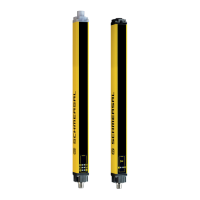
Describes the SLC440 as a non-contact safety guard for hazardous points/areas.
Lists the types and options available for the SLC440 safety light curtain.
Refers to specifications for non-standard versions matching the standard.
Details included mounting kits, spacers, and optional accessories.
Provides detailed specifications including standards, materials, and ratings.
Explains how response time is affected by field height, resolution, and coding.
Lists safety standards, PL, control category, PFH, and SIL values.
Describes system functions like protective mode, restart interlock, and blanking.
Explains automatic restart without external release when the field is clear.
Details how manual reset prevents automatic enabling of outputs after interruptions.
Describes using two command devices for safety in access monitoring applications.
Explains how to blank stationary objects in the protection field.
Allows compensation for slight position changes of blanked objects.
Allows blanking of movable objects, affecting effective resolution.
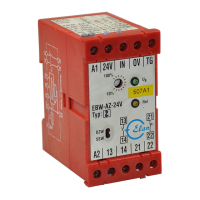
Monitors auxiliary contacts of contactors for malfunctions, locking outputs if detected.
Allows rotation of the 7-segment display via software for readability.
The system performs a self-test upon power-up and cyclically during operation.
Prevents mutual interference between adjacent safety light curtain systems.
Enables individual adjustment of functionality using a command device pushbutton.
Provides preventive guidelines for safe and appropriate handling of the SLC.
Defines the protection field and the necessity of additional protective devices.
Details the procedure for parallel alignment of transmitter and receiver.
Supports best possible alignment using a 7-segment display.
Defines the minimum distance to ensure safe stopping of hazardous movement.
Specifies minimum distances to avoid detection issues from reflecting surfaces.
Provides detailed dimensions for transmitter and receiver units.
Details mounting kits included and optional accessories for fixing.
Illustrates basic wiring connections for restart interlock and protective mode.
Shows a detailed wiring example for the SLC440 with safety monitoring module.
Lists pin assignments and descriptions for receiver, transmitter, and cables.
Lists essential checks required before initial operation of the SLC.
Emphasizes the importance of regular inspections for safety and injury prevention.
Recommends visual inspection and functional tests for component integrity.
Specifies checks to be performed every six months or after machine modifications.
Provides instructions for cleaning optics covers without disabling outputs.
Explains the function and LED colors for receiver and transmitter status indication.
Lists error codes displayed by the receiver and their corresponding actions.
Instructs to perform disassembly only in a de-energised condition.
Advises on proper disposal in accordance with national prescriptions and legislations.
Provides contact information for consultancy, sales, and repair handling.
| Brand | schmersal |
|---|---|
| Model | SLC440 |
| Category | Security Sensors |
| Language | English |