9
SLC440
Operating instructions
Safety light curtain
EN
3. Mounting
3.1 General conditions
The following guidelines are provided as preventive warning notices
to ensure a safe and appropriate handling. These guidelines are an
essential part of the safety instructions and therefore must always be
observed and respected.
The SLC must not be used on machines, which can be stopped
electrically in case of emergency.
The safety distance between the SLC and a hazardous machine
movement must always be observed and respected.
Additional mechanical safety guards must be installed so that the
operator has to pass by the protection field to reach the hazardous
machine parts.
The SLC must be installed so that the personnel always must be
within the detection zone when operating the machine. An incorrect
installation can lead to serious injuries.
Never connect the outputs to +24VDC. If the outputs are wired to
+24VDC, they are in ON state, as a result of which they are unable to
stop a hazardous situation occurring on the application/machine.
The safety inspections must be conducted regularly.
The SLC must not be exposed to inflammable or explosive gasses.
The connecting cables must be connected in accordance with the
installation instructions.
The fixing screws of the end caps and the mounting angle must be
firmly tightened.
3.2 Protection field and approach
The protection field of the SLC consists of the entire range located
between the protection field markings of transmitter and receiver.
Additional protective devices must ensure that the operator has to pass
by the protection field to reach the hazardous machine parts.
The SLC must be installed so that personnel are always located within
the detection zone of the safety device when operating the hazardous
machine parts to be secure.
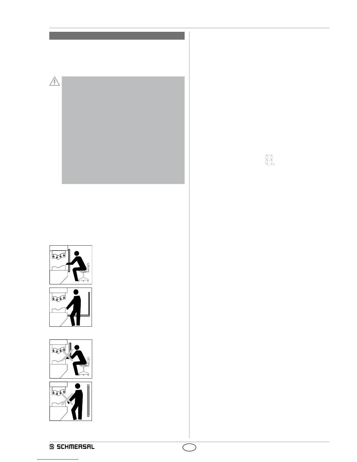
Correct installation
Hazardous machine parts can only be reached
after passing through the protection field.
The presence of staff members between the
protection field and hazardous machine parts
must be prevented/avoided (protection against
stepping over).
Unauthorised installation
Hazardous machine parts can be reached
without passing through the protection field.
The presence of staff members between the
protection field and hazardous machine parts
is enabled.
3.3 Alignment of the sensors
Procedure:
1. Transmitter and receiver must be fitted parallel to each other and at
the same height.
2. Choose the operating mode "Automatic" (see chapter Protective
mode/automatic) and switch the operating voltage on.
3. The 7-segment display in the receiver shows the current signal quali-
ty/fine setting (signalling, see chapter "set-up mode") for 30 seconds.
Rotate the transmitter and then the receiver towards each other until
you have the best possible signal strength of 3 horizontal bars (7
segment display) (note that 2 horizontal bars is sufficient). Fix this
position using the screws to the mounting angle.If the set-up is not
possible within 30 seconds, change to set-up mode (see chapter
"set-up mode").
The set-up mode leads to the best possible positioning of the sen-
sors through the basic setting (position of the second and last beam)
and the optimisation with the fine adjustment (total signal).
Status indication of the LED
OSSD ON (green) is active, signal strength (orange) is not active.
3.4 Setting mode
Setting tool with 7-segment display
The function supports the best possible alignment between transmitter
and receiver. The indication shows the signal strength of the different
receivers while the safety outputs are switched off. For the optical
indication of the signal strength two areas area available, the signal
strength of the second (with SLG first) and the last beam in the protec-
tion zone (default setting) as well as the best possible orientation of all
beams (find adjustment).
Activating setting mode
After the system start, a signal impulse (H signal 24 VDC) must be
present at the input restart interlock (pin 1) of the receiver for at least
2.0 seconds (pushbutton/enabling).
The 7 segment display starts with the default setting (vertical bar). The
sensors are aligned in parallel and at the same height until both seg-
ments have reached a signal strength of 50% to 100%.
With a signal impulse on the input release (pin 1) you can change be-
tween default setting and fine adjustment as long as the signal strength
is at 50% of the default setting (vertical bar).
After the setting of the sensors, the setting mode can be terminated
by the presence of a HI-signal at pin 1 for at least 2.5 seconds (max. 6
seconds) and the actuation of the enabling button or by a voltage reset
at the receiver (+UB).
Status display
The signal strength is also shown on the display in the diagnostic win-
dow by yellow light pulses to the status light. The better the alignment,
the higher the frequency of the light pulses. The alignment is correct
when the light pulses switch over to continuous light.
If there is no optical synchronisation between the transmitter and the
receiver, a light pulse is emitted every three seconds. The setting mode
is ended by a system start ( +UB OFF/ON).