Release restart
interlock
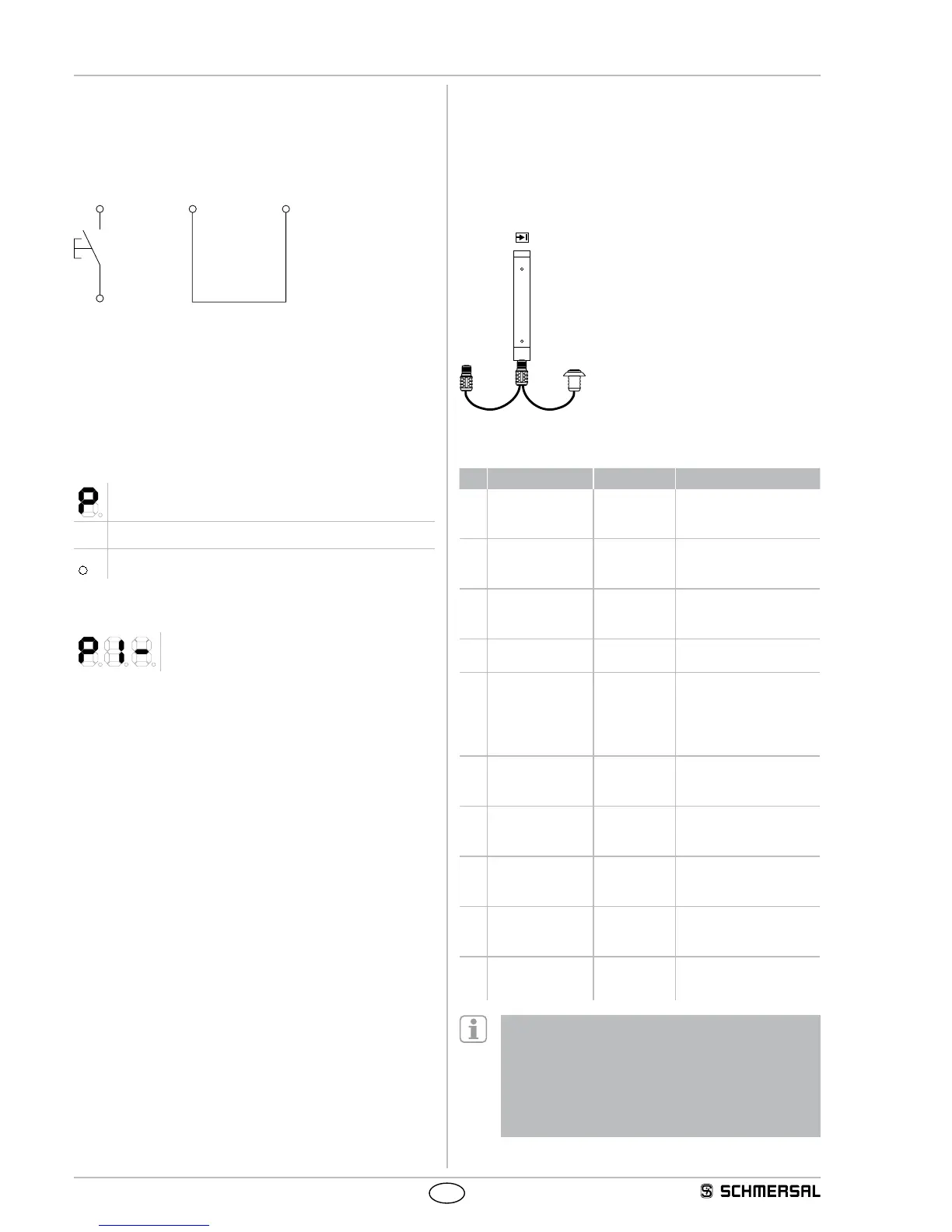
Wiring of the receiver
1 (restart interlock)
be removed. If the EDM function was activated, the auxiliary contact
of Pin 8 must be removed.
2) The receiver switches to parameter setting mode when the operating
voltage is switched on.
The operating status is signalled in the following way
7- segment display
● LED OSSD ON (red) active
● LED OSSD OFF (green) active
Parameter setting
repeatedly
- (Parameter P 1 not active, factory setting)
2) Select the desired parameter by means of command device S1
(briefly press the button)
3) Select the desired parameter by means of the command device
(press the button for a long time)
1. Push button (approx. 2.5 seconds) ➔ - flashes (parameter not active)
2. Enable button when ➔ A static (parameter active)
4) Save the new configuration with the parameter Save S.
(push the
button for a long )
1. Actuate button (approx. 2.5 seconds) ➔
S.
2. Enable button when ➔
S.
static
3. Automatic restart ➔ "segment circulation"
then P is displayed (saving operation successful)
If no restart takes place (S.), the saving operation has not been suc-
cessful (i.e. the parameter changes have not been saved).
The procedure 1 to 3 must be repeated.
All parameters can be reset to the factory setting using parameter C.
(clear/delete).
1) Press the button approx. 2.5 seconds) ➔ C. flashes
2) Enable the button when ➔ C. static
3) Automatic restart ➔ "Segment circulation", then P is displayed (all
parameters have been deleted)
Return to normal operating mode
1. Switch off the operating voltage at the receiver
2. Remove jumper connection at the receiver DOUT (Pin 6) and EDM
(Pin 8).
3. Select the desired operating mode (jumper connections)
4. Switch operating voltage on
Adapter cable for parameter setting
If the wiring for the parameter setting of the receiver is not accessi-
ble, the KA-0974 adapter cable can be used as an alternative. The
adapter cable is connected between the connecting cable and the
cable connector of the receive. The parameters are set by means of the
command device (pushbutton), as described in the parameter setting.
After the parameters have been set, the KA-0974 is removed and the
connecting cable is connected to the receiver.
Key
1 = Connecting cable Receiver
2 = Command device pushbutton
for release
Table Parameter setting
No. Parameter Status Note
P 1 Fixed blanking – = not active
A = Active
Position active saves all
interrupted beam through
Teach-in mode
P 2 Fixed blanking
with movable edge
region
– = not active
A = Active
Tolerance in edge region
± 1 beam - adjust safety
distance!
P 3 Floating blanking 1
beam or 2 beams
– = not active
1 = 1 beam
2 = 2 beams
Blanking of max.
2 beams - adjust safety
distance!
P 4 Contactor control/
EDM
– = not active
A = Active
The auxiliary (NC) con-
tacts are monitored
P 5 Double acknow-
ledgement with
command device
restart interlock
– = not active
A = Active
Operating mode "Pro-
tective mode with double
P 6 Beam coding A
(alternative)
– = not active
A = Active
Activating upon mutual
interference of identical
systems
P 7 Rotating the display
through 180 de-
grees
– = not active
A = Active
The orientation of the
7 segment display can be
turned through 180 degrees
S. Save S. Press button S1 to save
changes
(2.5...6.0 sec.)
C. Clear/delete C. Press button S1 to save
factory setting
(2.5...6.0 sec.)
d. Diagnostic/
setting mode
d. Switch to setting mode
P 1 oder P 2 - When fixed blanking is activated, all beams
that are interrupted in the protection field at the time that
command device S1 is actuated (> 2.5 sec. with trailing edge)
are blanked.
P 2 - Parameter combination P 1 and P 2 or P 2 and P 3 is
not authorised. Status indication n = not available
P 6 - Beam coding A must also be set at the transmitter, refer
to chapter Beam coding A