16
Operating instructions
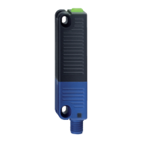
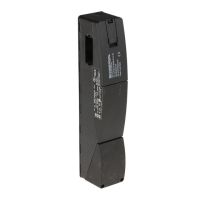
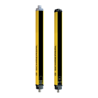
Safety light curtain
SLC440
EN
5.3 Regular check
A regular visual inspection and functional test, including the following
steps, is recommended:
1. The component does not have any visible damages.
2. The optics cover is not scratched or soiled.
3. Hazardous machinery parts can only be accessed by passing
through the protection field of the SLC.
4. The staff remains within the detection area, when works are conduct-
ed on hazardous machinery parts.
5. The safety distance of the application exceeds the mathematically
calculated one.
Operate the machine and check whether the hazardous movement
stops under the hereafter-mentioned circumstances.
1. Hazardous machine parts do not move when the protection field is
interrupted.
2. The hazardous machine movement is immediately stopped, when
the protection field is interrupted with the test rod immediately before
the transmitter, immediately before the receiver and in the middle
between the transmitter and the receiver.
3. No hazardous machine movement when the test rod is within the
protection field.
4. The hazardous machine movement comes to standstill, when the
voltage supply of the SLC is switched off.
5.4 Half-yearly inspection
The following items must be checked every six months or when a
machine setting is changed.
1. Machine stops or does not inhibit any safety function.
2. No machine modification or connection change, which affects the
safety system, has taken place.
3. The outputs of the SLC are correctly connected to the machine.
4. The total response time of the machine does not exceed the re-
sponse time calculated during the first putting into operation.
5. The cables, the connectors, the caps and the mounting angles are in
perfect condition.
5.5 Cleaning
If the optics cover of the sensors is extremely soiled, the OSSD outputs
can be disabled. Clean with a clean, soft cloth with low pressure.
The use of agressive, abrasive or scratching cleaning agents, which
could attack the surface, is prohibited.
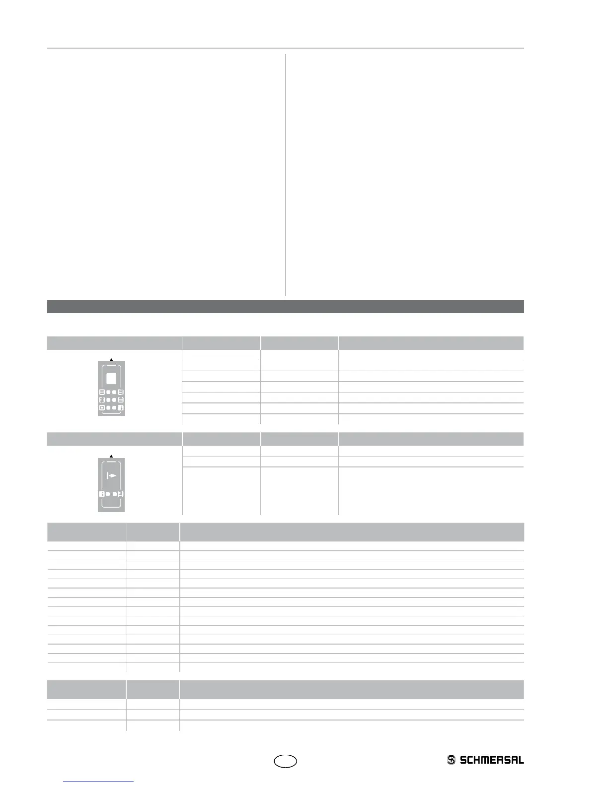
6. Diagnostic
6.1 Status information LED
Receiver Function LED colour Description
OSSD ON
OSSD OFF
Restart
Signal reception
Blanking
Information
Protection field
OSSD ON green Safety outputs Signal condition ON
OSSD OFF red Safety outputs Signal condition OFF
Restart yellow Input for command device
Signal reception orange Safety-monitoring module of Signal reception
Blanking blue Protection field(s) inactive (blanking)
Information yellow-green Beam coding A
Transmitter Function LED colour Description
Information Transmitting
Protection field
Information green Function display, Beam coding A
Transmitting orange Transmitter active
Receiver
LED Status LED Description
OSSD ON On Protection field clear
OSSD OFF On Protection field interrupted, system or configuration error
On Error output refer to Fault diagnostic table
Restart On Restart interlock (manual reset) active, signal expected at input restart interlock
Signal reception ON/flashing Signal reception too low, check alignment and installation height between transmitter and receiver
Cleaning the black profile cover
OFF Alignment between transmitter and receiver OK, when the OSSD are enabled
Blanking 1 flash Fixed blanking of the protection field(s)
2 flash Floating blanking, max. 1 beam
3 flash Floating blanking, 2 beams
4 flash Floating (max. 1 beam) and fixed blanking of protection field(s)
5 flash Floating (2 beams) and fixed blanking of protection field(s)
6 flash Fixed blanking with movable edge region
Information flashing Beam coding A is active
Transmitter
LED Status LED Description
Transmitting On Standard operation, transmitter active
flashing Configuration error
Information flashing Beam coding A is active
 Loading...