Do you have a question about the schmersal RSS 36-D-ST and is the answer not in the manual?
Describes the basic function of the safety sensor and its role in monitoring guards.
Specifies that operations must be carried out by trained specialist personnel authorized by the plant operator.
Explains the meaning of symbols used in the manual for warnings, cautions, and information.
Clarifies that products are intended for industrial use as part of machines, not for private consumers.
Outlines the need to observe all safety instructions, country-specific standards, and regulations.
Details the structure of the product's ordering code and the meaning of its different components.
Explains specifications that apply to special versions not explicitly listed in the standard ordering code.
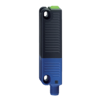
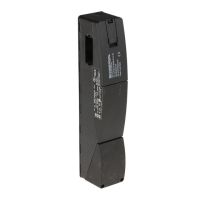
Describes the sensor's design for application in safety circuits and monitoring movable safety guards.
Warns about potential hazards and damages to machinery from improper use or manipulation of the switchgear.
States the manufacturer's liability limitations regarding defective mounting or unauthorized modifications.
Provides switching distances required for safe operation, detailing values for different sensor/actuator combinations.
Details connection types, pin configurations, and cable considerations for the sensor.
Lists operational ambient conditions, temperature ranges, and relevant insulation values.
Specifies parameters for safety digital inputs, including voltage, current, and test pulse characteristics.
Details parameters for safety digital outputs, including voltage, current, and switching capacity.
Lists relevant electromagnetic compatibility (EMC) standards that the device complies with.
Provides general instructions and references to standards for mounting the safety sensor and actuator.
Shows detailed dimensional drawings of the safety sensor and actuator for installation planning.
Lists available accessories for mounting, such as screws and sealing kits, which must be ordered separately.
Details typical and assured switching distances required to ensure the safety function is correctly activated.
Explains the recommended adjustment procedure for the sensor and actuator to ensure proper detection.
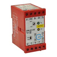
Covers general principles for integrating safety outputs into control systems and wiring requirements.
Details cable design requirements and considerations for serial diagnostic (SD) connections.
Illustrates common series-wiring configurations for safety sensors with diagnostic outputs.
Provides pin configurations, color codes, and ordering information for connecting cables and connectors.
Describes the "teach-in" procedure for coding safety sensors and actuators for secure pairing and operation.
Explains how the safety outputs function to ensure safety when a guard is opened or the actuator is removed.
Describes the function of the diagnostic LEDs for indicating operating status, supply voltage, and faults.
Explains the use of the diagnostic output (OUT) for visualization and control tasks in a PLC.
Details how safety sensors with serial diagnostic function are wired in series for data evaluation via gateways.
Recommends regular visual inspection and functional tests for maintenance-free operation and safety.
Specifies that the safety switchgear must be disassembled only when the system is in a de-energised condition.
Advises on proper disposal methods for the safety switchgear in accordance with national regulations.
| Protection Class | IP67 |
|---|---|
| Operating Temperature | -25°C to +70°C |
| Housing Material | Plastic |
| Connection Type | M12 connector |
| Number of Safety Contacts | 2 |
| Rated Voltage | 24 V DC |
| Sensor Type | RFID |
| Safety Standards | EN ISO 13849-1 |
| Current Rating | 200 mA |
| Contact Configuration | NO/NC |