7
SLC440
Operating instructions
Safety light curtain
EN
2.8.7 Contactor control (EDM)
The contactor control monitors the controlled switching elements
(auxiliary contacts of the contactors) of both outputs. This monitoring
is realised after each interruption of the protection field and prior to the
restart (enabling) of the outputs. In this way, malfunctions of the con-
tactors are detected, e.g. contact welding or contact spring breakage.
If the light curtain detects a malfunction of the switching elements, the
outputs are locked.
After elimination of the error, a power reset is required.
The contactor control is not activated upon delivery. The
function is activated in parameter setting mode (P 4).
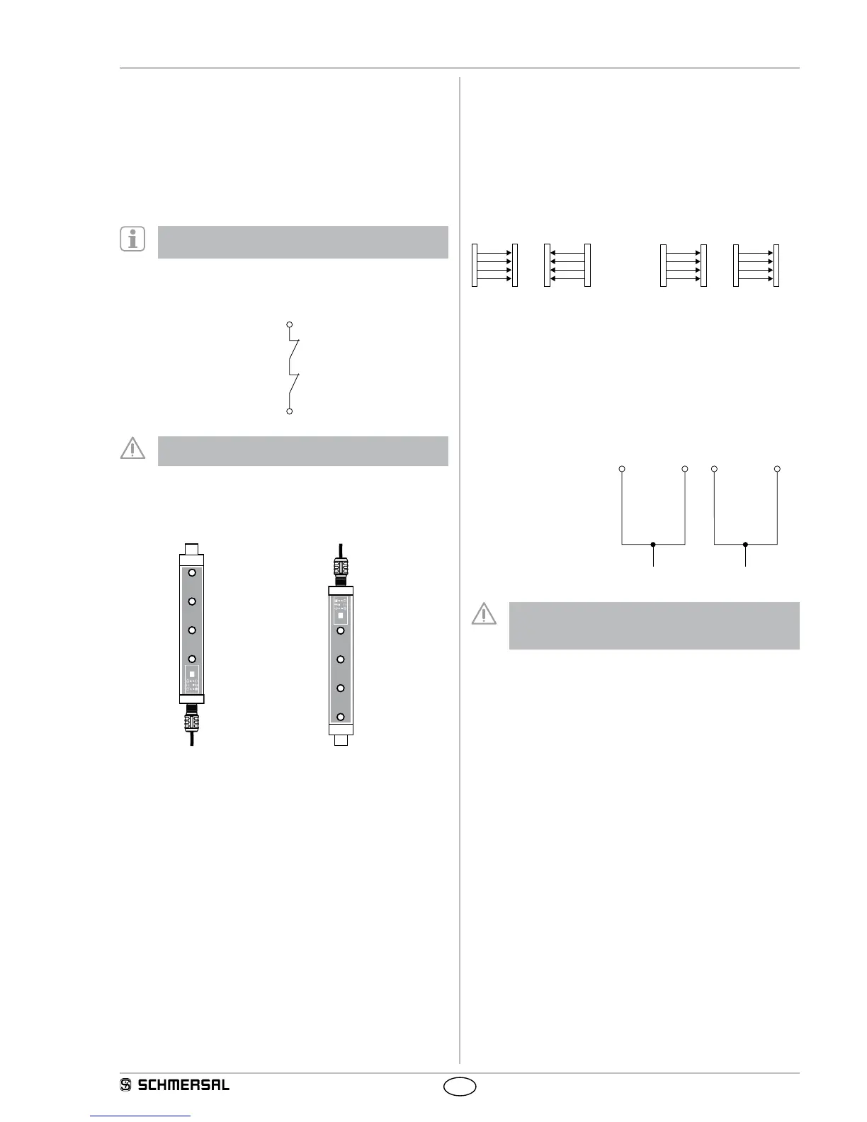
Connection EDM
Wiring of the receiver
- Kn1, Kn2 = auxiliary contact
of the last switching relay
The auxiliary contacts must only be connected,
when the function is activated!
2.8.8 Rotating the display through 180 degrees
The orientation of the 7 segment display can be rotated through
180 degrees via the software option. This ensures that the display
remains readable in rotated mounting positions of the AOPD.
Parameter P 7 –
Display normal orientation
Parameter
P 7 A
Display rotated
2.9 Self-test
The system performs a complete self-test and safety test within
2 seconds after the operating voltage has been switched on. If the pro-
tection field is free, the system switches to the ON condition (automatic
mode). In case of an error, the outputs at the receiver do not switch to
the ON state. An error message is emitted in the form of an error code.
For more information, refer to chapter Fault diagnosis.
During operation, the system executes a cyclic self-test. Safety-rele-
vant faults are detected within the reaction time and cause the outputs
to be switched off and an error code to be emitted.
2.10 Beam coding A
The preset beam coding of the safety light curtain must be adjusted,
when systems operating in each other's vicinity and a set-up as shown
in the image below (no interference) is impossible. When supplied, the
beam coding A is not active. A receiver with activated beam coding A
can distinguish the beams of the transmitter with the same beam cod-
ing, which are destined to this particular receiver, from foreign beams.
If adjacent systems are operated without beam coding A,
the user is at risk.
no interference
Interference:
beam coding A required!
receiver by means of flashing LED's (refer to LED status information).
each sensor (receiver and trans-
mitter) individually.
The function at the receiver is activated in parameter setting mode (P 6).
Transmitter parameter setting
Wiring of the transmitter
Jumper connection
pin 1 with pin 2
Jumper connection
pin 3 with pin 4
The response time of the system is increased when beam
coding A is used. To this end, the safety distance must be
adjusted.
Refer to chapter: Response time.
2.11 Parameter setting
The parameter setting of the SLC440 enables the individual adjustment
of the desired functionality to the application.
Parameter display (7-segment display)
A = parameter active
- = parameter not active
S. = save the current configuration
C. = delete the current configuration, new configuration = factory setting
n = unavailable (unauthorised setting, refer to Parameter setting infor-
mation)
d. = diagnostic/setting mode
Parameter selection
Selection, change and acceptance of the parameters by means of the
command device pushbutton S1:
- Switch to parameter setting Px briefly press the button
0.1 … 1.5 sec.
- Change parameter setting Px press button 2.5 … 6 sec.
- Save S. /Factory setting C. press button 2.5 … 6 sec.