4
Operating instructions
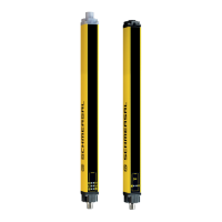
Safety light curtain
SLC440
EN
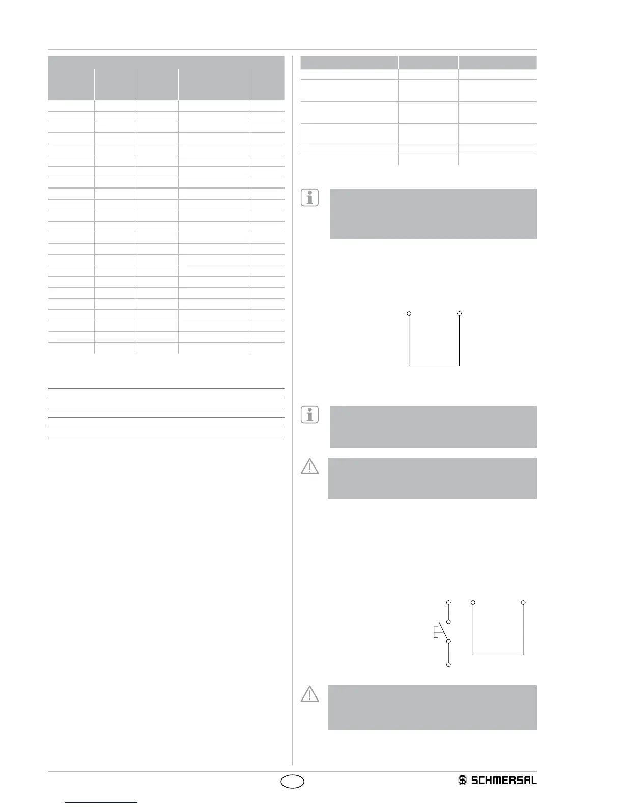
Resolution 30 mm
Protection
field height
[mm]
Beams
(Lines)
[Number]
Response
time
[ms]
Response time
with Beam coding
A [ms]
Weight
[kg]
170 8 10 15 0.4
250 12 10 15 0.5
330 16 10 15 0.6
410 20 10 15 0.8
490 24 10 15 0.9
570 28 10 15 1.0
650 32 10 15 1.1
730 36 10 15 1.2
810 40 10 15 1.4
890 44 10 15 1.5
970 48 10 15 1.6
1050 52 20 27 1.7
1130 56 20 27 1.8
1210 60 20 27 2.0
1290 64 20 27 2.1
1370 68 20 27 2.2
1450 72 20 27 2.3
1530 76 20 27 2.4
1610 80 20 27 2.6
1690 84 20 27 2.7
1770 88 20 27 2.8
1850 92 20 27 2.9
1930 96 20 27 3.0
2.7 Safety classification
Standards: EN ISO 13849-1, EN 62061
PL: up to e
Control category: up to 4
PFH value: 5.14 x 10
-9
/ h
SIL: up to 3
Service life: 20 years
2.8 Functions
The system consists of a receiver and a transmitter. For the described
functions, no further switching elements are required.The diagnostic
and function selection takes place with a command device (key re-
lease), refer to the chapter on parameterisation.
The system has the following features:
(automatic start after release of the protection zone)
Factory setting
The system features many functions without needing any additional
devices. The following table gives an overview of the possible functions
and the factory settings configuration.
Function Factory setting Configuration
Protective mode, automatic not active External wiring
Restart interlock
(manual reset)
not active External wiring
Double acknowledgement/
reset
not active with command device
Blanking fixed/floating not active with command device
Contactor control (EDM) not active with command device
Beam coding A not active with command device
By default neither the restart interlock (manual reset) nor the
protective mode is active. One of both operating modes must
be wired in order to enable the OSSD outputs. If no opera-
ting mode is selected, the following message is shown:
Status indication E1 + LED OSSD OFF (red)
2.8.1 Protective mode / Automatic
The protective mode switches the OSSD outputs to the ON state
(protection field not interrupted), without external release of a switching
device.
Wiring of the receiver
Jumper connection
pin 1 with pin 6
This operating mode generates an automatic restart of the machine if
the protection field is not interrupted.
A 24 VDC H-signal at the input of pin 1 leads to a restart of
the system. If the 24 VDC H-signal is still present at pin 1
after the self-test, the system switches to setting mode,
see chapter "Setting mode".
This operating mode may only be chosen in conjunction
with the restart interlock (manual reset) of the machine.
This operating mode must not be chosen, when persons
can step behind the protection field.
2.8.2 Restart Interlock (operation)
The restart interlock (manual reset) prevents an automatic enabling of
the outputs (OSSD's ON state) after switch-on of the operating voltage
or an interruption of the protection field. The system switches the
outputs only to ON state, when an external command device (restart
button) generates an enabling signal at the restart input (receiver).
Wiring of the receiver
- Jumper connection pin 5 with pin 6
- Command device (enabling button)
at pin 1
+24VDC