5
SLC440
Operating instructions
Safety light curtain
EN
2.8.3 Restart interlock with double acknowledgement/reset
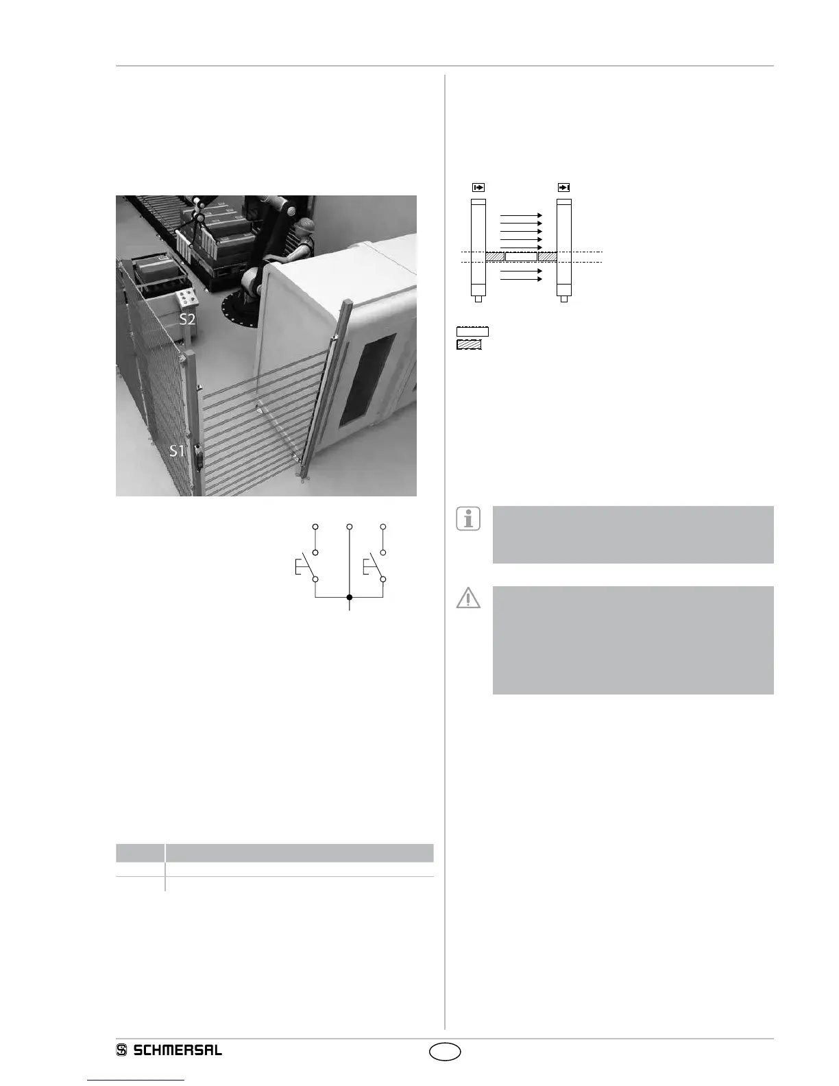
In applications with access monitoring, a complete overview of the haz-
ardous areas is often not possible; despite that, a reset of the command
device for the restart interlock outside of the hazardous area by third
parties is at all times enabled, although possible persons/operators
are in the invisible area. This hazardous situation can be avoided by
means of a double reset, i.e. integration of two command devices inside
and outside the hazardous area.
Wiring of the receiver
- Command device S1 at pin 1
- Command device S2 at pin 5
- Pin 6, no signal (input open)
S1
Specification
The operating mode is available, when the parameter setting -
double reset is activated (P 5). See chapter Parameter setting.
Sequence for enabling:
1) Actuate command device inside of the hazardous area (S2) and
leave the hazardous area
2) Go through protected field or interrupt at least one beam, then
release protected field
3) Actuate the command device outside of the hazardous area (S1)
Command device S1 can be reset (acknowledged) within a timeframe
of 2 to 60 seconds after the actuation of S2. If the order or the time
requirement is not respected, the process must be repeated.
Signaliling: LED restart (yellow)
Status Note
On Release of S2 (restart interlock 2) waiting for signal
Flashing Release of S1 (restart interlock) waiting for signal
2.8.4 Fixed blanking
The SLC440 can blank stationary objects in the protection field.
Multiple protection field areas can be blanked. If small changes are
made within the fixed blanking area, each time 1 beam can be addition-
ally blanked to increase the tolerance. See chapter Parameter setting
- Fixed blanking with movable edge regions (P 2).
Fixed blanking area
E1 R1
Key
Object in protection field
mechanical cover
The range of the fixed blanking can be arbitrarily chosen in the
protection field.
The first beam line, which realises the optical synchronisation and is
located immediately behind the diagnostic window, cannot be blanked.
The area of the fixed blanking must not be modified after the teach-in
process. Any change of the area or removal of the object from the
protection field will be detected by the system. As a result, the outputs
are disabled (locked). This locking can be neutralised by executing a
new teach-in process in accordance with the actual beam interruptions.
The function is activated by means of the parameter setting
(P1). If the function is activated, the LED blanking in the
diagnostic window of the receiver starts flashing.
See chapter Parameter settings.
The remaining lateral areas must be protected against
intrusion by means of mechanical covers.
The lateral covers must be fixed with the object.
Partial covers are not authorised.
After the fixed blanking, the protection field must be tested
by means of the test rod.
The restart interlock function of the safety light curtain
or the machine must be activated.
2.8.5 Fixed blanking with movable edge region
This function can compensate slight position changes of one fixed
blanked object with a change of ± 1 beam. This position change cor-
responds to an amplitude of approx. ± 10 mm resolution 14 mm and
approx. ± 20 mm resolution 30 mm upwards and downwards in the
protection field.