Instructions for Use – SCHMIDT
®
Flow Sensor SS 20.600 Page 11
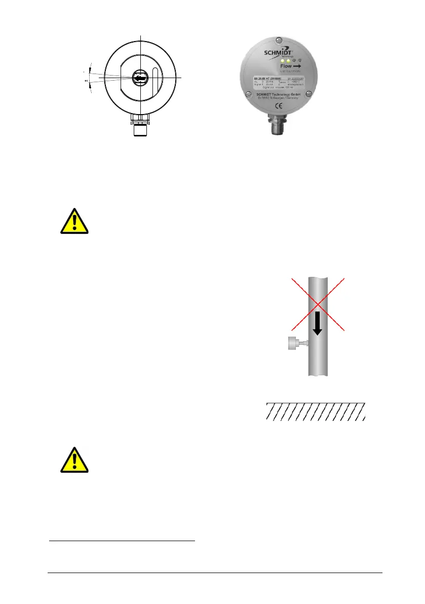
Figure 3-2 Arrangement of flow direction arrows
The design of the sensor element results in a minimal coupling be-
tween heater and medium temperature sensor, leading to a thermal
crosstalk at minimal flow velocity near zero that defines the lower limit
of the measuring range.
Due to system characteristics the lower measuring range limit
of the sensor is 0.2 m/s.
Under unfavourable installation conditions, free convection may in-
crease the crosstalk between heater and temperature element on the
sensor chip and therefore the lower detection limit:
Measurements in a downward flow
(downdraft flow, see Figure 3-3) lead to
considerably increased measuring val-
ues in the lower flow range.
The area concerned depends on the
system pressure. Correct measuring
values are displayed above
6
2 m/s.
Avoid installation in a pipe or chamber with downward flow be-
cause the lower measuring range limit can rise significantly.
In case of a vertical downdraft flow and an overpressure of 16 bar.