Instructions for Use – SCHMIDT
®
Flow Sensor SS 20.600 Page 16
Quasi-parabolic flow profile
The system length is large compared to the cross-section surface and
the flow velocity is so high that the ratios correspond to that of the cir-
cular pipe. This means that the same requirements apply here to the
installation conditions.
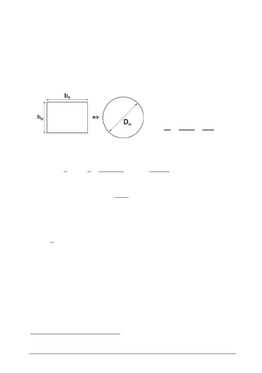
Since the situation is similar to that in a pipe
, the volume flow in a
square chamber can be calculated by equating the hydraulic diameter
of both cross-section forms. The result for a rectangle “R” according to
Figure 3-5 is a hydraulic “pipe diameter” D
H
:
b
R
: Width of rectangular channel
h
R
: Height of rectangular channel
D
H
: Hydraulic pipe diameter
Figure 3-5
According to this, the volume flow in a shaft is calculated as:
Width/height of the square chamber [m]
Hydraulic inner diameter of the chamber [m]
Cross-section area of the equivalent pipe [m
2
]
Maximum flow velocity in the middle of the pipe [m/s]
Average flow velocity in the pipe [m/s]
Standard volume flow [m
3
/s]
Typical applications are:
o Ventilation shaft
o Exhaust air duct
The profile factors are equal for both cross-section forms.