7
Montage- und Betriebsanleitung für
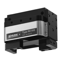
2-Finger-Parallelgreifer
Type RH 918 / RH 9010
Assembly and Operating Manual for
2-Finger-Parallel-Gripper
Type RH 918 / RH 9010
Mounting and adjustment of the proximity switches
NOTE:
The switching lug and the screws for the inductive monitoring are
provided in an enclosed pack with the gripper.
Before installing the inductive monitoring, please read and com-
ply with the safety instructions.
1. Fasten the switching lug to the base jaw (1 x M 2.5).
2. Move gripper to »OPEN« position.
3. Push the proximity switch into the Ø 4 hole of the bracket
(gripper »OPEN«) until the proximity switch is in contact with
the switching lug.
4. Pull the proximity switch back about 0.2 – 0.4 mm and fasten
the proximity switch with the M3 set screw.
(Caution: The max. tightening torque is 100 Ncm)
5. Move gripper to »CLOSED« position, push 2nd proximity
switch into the Ø 4 hole (gripper »CLOSED«), adjust and
secure as described in steps 3 – 4.
For fine adjustment you can move the brackets in the slot.
Secure the set screws and the screws for the switching lug with
Loctite 243.
Hub pro Finger / Stroke per finger
5 10 15 20 25 30 mm
OFFEN / OPEN
GESCHLOSSEN / CLOSED
Abfragebereich
Monitoring range
braun / brown
s
chwarz / black
b
lau / blue
Last
Payload
S
chließer
Closer
Gewindestifte M3
Set screws M3
Schraube für Schaltfahne
Screw for control cam
Schraube für Schaltfahne
Screw for control cam
Schaltfahne
Control cam
Schaltfahne
Control cam
0,2 - 0.4 mm
Näherungsschalter – Greifer »AUF«
Proximity switch – Gripper “OPEN”
Näherungsschalter
Greifer »Auf«
Näherungsschalter – Greifer »ZU«
Proximity switch – Gripper “CLOSED”
Schaltfunktion: in unbedämpftem Zustand gezeichnet
Output: drawn in non-actuated condition
Montage und Einstellen der Näherungsschalter
HINWEIS:
Die Schaltfahne und die Schrauben für die induktive Abfrage wer-
den als Beipack mit dem Greifer geliefert.
Bevor Sie die induktive Abfrage installieren, lesen und beachten
Sie bitte die Sicherheitshinweise.
1. Befestigen Sie die Schaltfahne an der Grundbacke (1 x
M 2.5).
2. Greifer in Stellung »OFFEN«.
3. Schieben Sie den Näherungsschalter in die Bohrung Ø 4 der
Halterung (Greifer »OFFEN«), bis der Näherungsschalter die
Schaltfahne berührt.
4. Ziehen Sie den Näherungsschalter um ca. 0.2 – 0.4 mm
zurück und fixieren Sie den Näherungsschalter mit dem
Gewindestift M3.
(Achtung: Das max. Anzugsmoment beträgt 100 Ncm)
5. Greifer in Stellung »GESCHLOSSEN«, den 2. Näherungs-
schalter in die Bohrung Ø 4 (Greifer »GESCHLOSSEN«),
einstellen und fixieren wie von 3. – 4. beschrieben.
Zum Feineinstellen können Sie die Halterungen im Langloch ver-
schieben.
Sichern Sie die Gewindestifte und die Schraube für die Schalt-
fahne mit Loctite 243.