SEL-487V Data Sheet Schweitzer Engineering Laboratories, Inc.
4
Protection Features
Phase-Voltage Differential
Elements
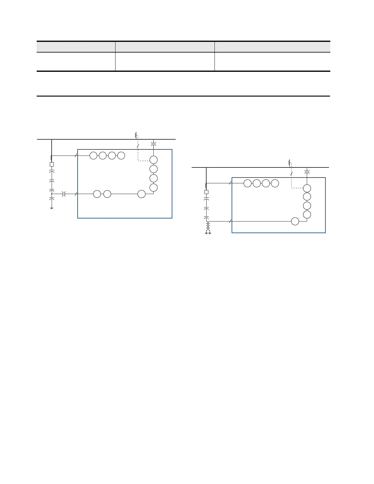
Figure 2 Phase-Voltage Differential One-Line Diagram
The SEL-487V provides three phase-voltage differential
elements. These elements are used to measure voltage
differences between bus or line phase voltages and the
tapped voltage of the grounded wye capacitor bank. Each
phase-voltage differential element is provided with a
differential voltage-nulling algorithm, referred to as the
KSET function. A KSET command is issued to the relay
via serial or Telnet communications. Once received by
the relay, the KSET command acts to zero out any
existing voltage differential. The KSET function is
intended to provide a means for removing small voltage
differential levels due to variations in individual
capacitor elements from manufacturing, potential
transformer, or CCVT measurement error.
Each phase differential element is provided with three
levels of detection, each with its own definite-time delay.
A low-set alarm level, trip pickup level, and high-level
trip pickup are provided.
The phase differential elements are used to detect
variations in capacitor bank impedance, due to loss of
individual capacitor elements, an entire capacitor can or
an entire group of capacitor cans. Two cycle cosine
filtering is used to minimize voltage transients due to line
switching operations.
Neutral-Voltage Differential
Elements
Figure 3 Neutral-Voltage Differential One-Line Diagram
The SEL-487V provides three neutral-voltage
differential elements for protection of up to three
ungrounded wye capacitor banks. The neutral-voltage
differential elements of the SEL-487V calculate zero-
sequence voltage from the three-phase potential inputs
provided from the line or bus. The zero-sequence voltage
is then compared to the zero-sequence voltage measured
by a potential transformer connected between the
capacitor bank neutral and ground. As with the phase
differential elements, the neutral-voltage differential
element uses a KSET nulling function to eliminate
differential voltage caused by manufacturing tolerances
of the capacitor bank and voltage measurement devices.
Sensitive measurement of the inputs allows as little as 30
millivolts of differential voltage to be detected.
Each neutral-voltage differential element is provided
with three pickup levels with independent definite-time
delay. The three levels provide alarm, trip, and
catastrophic failure protection for the capacitor bank.
CTL Automatic Voltage Control 3
59T Inverse-Time Overvoltage Elements
Table 1 Protection Elements (Sheet 2 of 2)
Element ANSI Number Description Quantity
87
V
27
P,Q
59
P,Q
32
PF
27
P,Q,G
59
P,Q,G
81
O,U
3
3
13
SEL-487V
IAW, IBW, ICW
VAY, VBY, VCY
IX1
VAZ, VBZ, VCZ
46
50
P, Q, G
51
P, Q, G
50
BF,FO
Line
Busbar
52
87
V
32
PF
27
P,Q,G
59
P,Q,G
81
O,U
3
1
13
SEL-487V
IAW, IBW, ICW
VAY, VBY, VCY
IX1
VAZ
46
50
P, Q, G
51
P, Q, G
50
BF,FO
Line
Busbar
52