Getting Started With the SEL-3355-2 Date Code 20180212
2
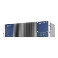
Product Overview
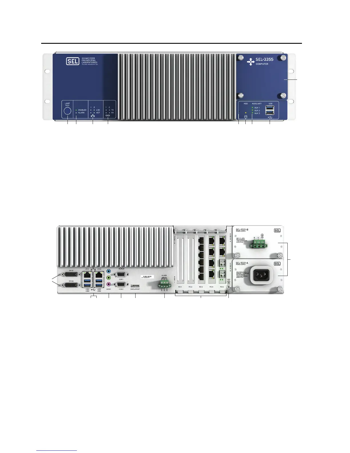
q LAMP TEST Button. Press and hold to test front-panel LEDs. Can be programmed to be an on/off or reset button.
w ENABLED and ALARM LEDs provide operational status. A green ENABLED LED indicates normal operation.
The ALARM LED illuminates red when a nonoptimal system condition exists.
e ETHERNET Status Indicators. Link (LNK) indicates that the port is connected, and activity (ACT) indicates when data
are being transmitted and received.
r SERIAL Status Indicators. Transmit (TX) and receive (RX) LEDs indicate activity on serial ports.
t PINHOLE Button. Provides reset and power functions; requires a pushpin to prevent accidental use.
y HDD Activity Indicator. Illuminates when SATA drives are accessed.
u AUXILIARY Status Indicators. Three programmable, bicolor LEDs for your custom application.
i USB Ports. Two easily accessible ports to connect USB 3.1 peripherals.
o SATA Drive Bay. Removable cover plate enables easy access to SATA drives from the front panel.
q DVI-D. Connect digital monitors by using native DVI or an HDMI adapter.
w ETH1 and ETH2. Onboard independent Gigabit Ethernet interfaces.
e USB Ports. Connect as many as four USB 3.1 peripherals at the rear panel.
r AUDIO Ports. Line Input (blue), Line Output (green), and Microphone Input (pink).
t COM1 and COM2. Standard EIA-232 serial ports with configurable +5 Vdc power on Pin 1.
y DISPLAYPORT. Connect new digital monitors supporting the DisplayPort interface.
u ALARM. The Form C alarm contact output can be wired either normally closed or normally open.
i PCI Expansion Slots. Install SEL or third-party PCI or PCI Express expansion cards for additional network, serial,
or other application-specific I/O.
o Earth Ground Terminal Screw. The earth ground connection for the SEL-3355-2.
a POWER Supply Modules. The rated input voltage is clearly marked on the chassis near the terminals.
q w
e r
yt
u i
o
a
q
ytr
ew
iu
o