43
Overview
SP 500 / 750-15 / 750-18 / 1000 / 1250 Operation Manual
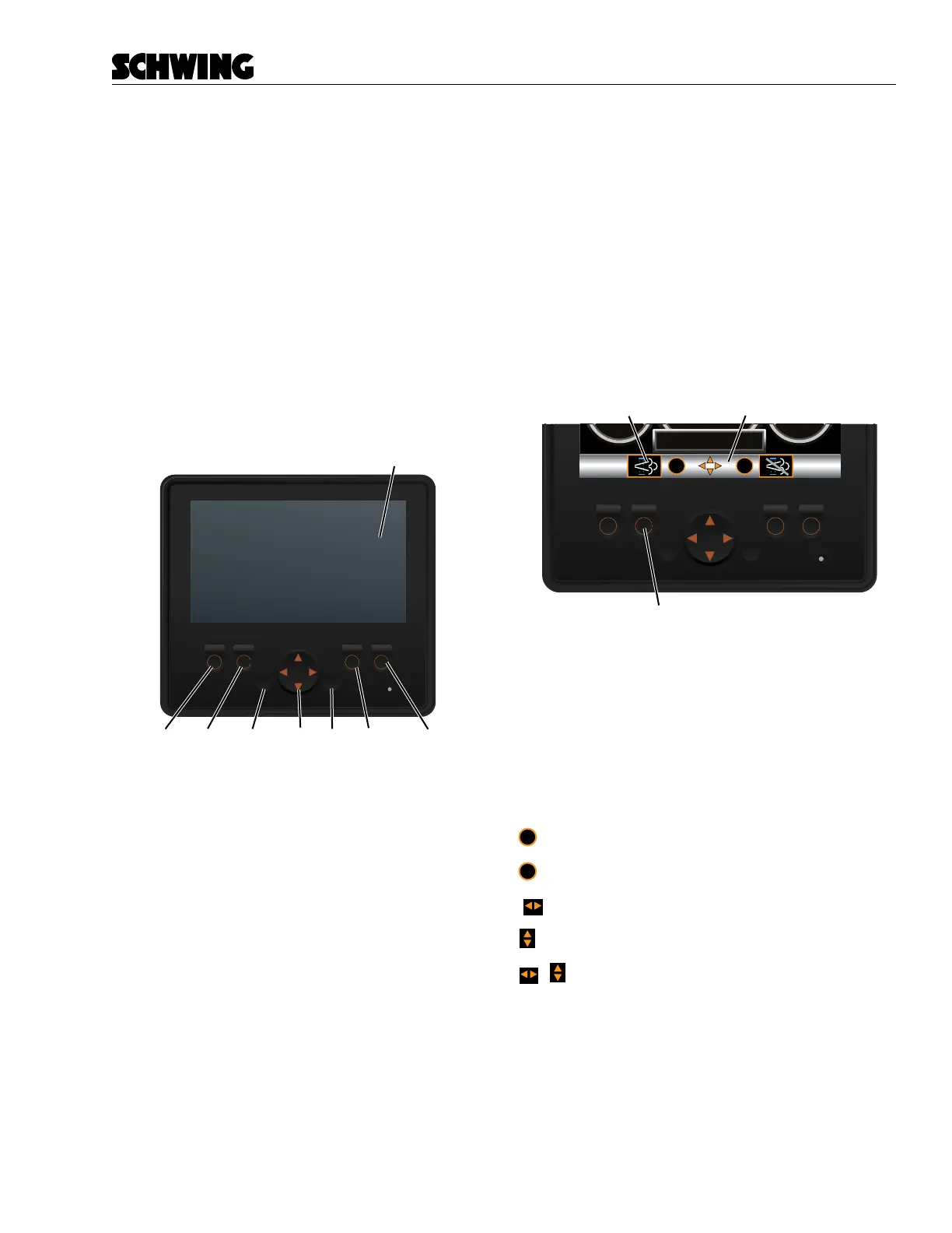
HMI (Human Machine Interface)
The HMI is primary interface between the operator and
the concrete pump. From the HMI, operators can view
and set machine parameters.
The HMI contains the following:
A. LCD Screen
B. (F1) Function Button
C. (F2) Function Button
D. (F3) Function Button
E. (F4) Function Button
F. ESC Button
G. OK Button
H. Navigation Arrows Button
A
E
D
B
C
F
G
H
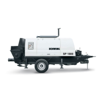
Navigation Pane
The Navigation Pane displays the available functions
and menu actions for each screen. If the “OK” symbol
appears on the Navigation Pane, the operator can push
the “OK” button to execute a menu action. If a symbol
appears above a Function Button, pressing that button
will activate the function.
Example: The Forced Regeneration-Start symbol ap-
pears above the (F2) Function Button. Pressing this
button will activate the Forced Regeneration-Start func-
tion.
%s
%s
okesc
Navigation Pane
Avaliable
Function Symbol
(F2) Function Button
Arrows in the center of the Navigation Pane, represent
which direction you can push the Navigation Arrows
button. The Navigation Arrows button can be pushed in
four directions. Not all directions are available on every
screen. This button is used to navigate to other screens
or to scroll through menu items.
To assist the reader, we will represent the symbols as
follows:
ok
= OK
esc
= Escape
= Navigation Arrows Left/Right
= Navigation Arrows Up/Down
= Navigation Arrows Left/Right /Up/Down