115
Maintenance
SP 500 / 750-15 / 750-18 / 1000 / 1250 Operation Manual
Set accumulator pressure cut-o
Read the pressure on the accumulator circuit pressure
gauge. The pressure should read 200 bar (2900 PSI).
If pressure adjustment is needed, follow these steps:
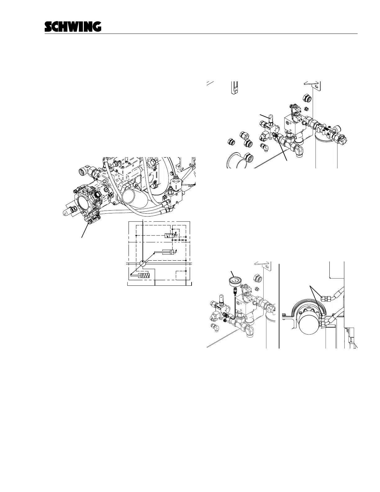
1. Stop the engine and follow “Lock Out - Tag Out
procedure” on page 92.
2. Loosen the jam nut on the pressure regulator of
the accumulator hydraulic pump (Figure 42). Turn
the screw in (clockwise) to increase the pressure
or out (counterclockwise) to decrease pressure.
Lock the jam nut when the pressure is correct.
Accumulator Pump
Pressure Cut-off Screw
200 bar
Figure 42
Accumulator pressure cut-o screw
3. Read the pressure on the accumulator gauge. It
should read the proper accumulator system pres-
sure.
Set the agitator pressure.
The agitator circuit relief valve is on the hydraulic tank
and is factory set to 200 bar (1812 PSI).
Agitator/Auxiliary
Pressure Relief
Gauge Port
Figure 43
Agitator valve pressure relief
To adjust the agitator relief valve:
1. Stop the engine and follow “Lock Out - Tag Out
procedure” on page 92.
2. Install a 0–600 bar gauge in the agitator valve re-
lief test port. Make sure the whip hose connection
is tight. Cap o the agitator (Figure 44).
Pressure Gauge
Cap Plugs
Figure 44
Install pressure gauge in agitator circuit