EasyManua.ls Logo

Scotsman AFE424W1A - User Manual

Scotsman AFE424W1A
25 pages
Print Icon
To Next Page IconTo Next Page
Loading...
INTRODUCTION
To the owner or user: This service manual is
intended to provide you, and the maintenance or
service technician, with the information needed to
install, start up, clean, maintain and repair this
product.
The AFE424 is an ice machine that produces
flaked ice and stores it in a insulated bin. It
automatically maintains the level of ice by turning
on when the ice level falls and switches off when it
is full.
This unit in serviceable in place; the ice storage bin
and hood may be removed from the chassis to
allow service access without removing the ice
machine from its installed location. The
refrigeration system uses R-134a as the
refrigerant.
Keep this manual for reference.
AFE424
March 2012
Page 1
Table of Contents
Specifications ··········································· Page 2
For The Installer: Environmental Limitations ··························· Page 3
Installation: ············································ Page 4
Installation: ············································ Page 5
Installation ············································ Page 6
Removal of the Cabinet ······································ Page 7
Component Location ······································· Page 8
Electrical Sequence ······································· Page 9
Initial Start Up ··········································· Page 10
Maintenance and Cleaning ···································· Page 11
Maintenance and Cleaning ···································· Page 12
Maintenance and Sanitation ··································· Page 13
Water Schematic ········································· Page 14
Refrigeration Schematic ····································· Page 15
Service Diagnosis: Condition - No Ice Being Produced ····················· Page 16
Service Diagnosis: Condition - No Ice Being Produced ····················· Page 17
Technical Characteristics ····································· Page 18
Removal And Replacement - Bin Thermostat ·························· Page 19
Removal And Replacement - Gearmotor Assembly ······················· Page 20
Removal And Replacement ··································· Page 21
Water Seal Installation - all models ································ Page 22
Removal And Replacement - Gearmotor Assembly ······················· Page 23
Removal and Replacement - Evaporator ····························· Page 24
Removal and Replacement: Refrigeration System ························ Page 25
Question and Answer IconNeed help?

Do you have a question about the Scotsman AFE424W1A and is the answer not in the manual?

Overview

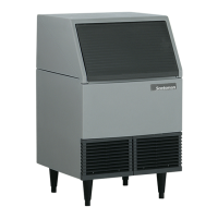
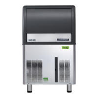
The AFE424 is an ice machine designed to produce flaked ice and store it in an insulated bin. It features automatic ice level maintenance, turning on when the ice level drops and switching off when the bin is full. This unit is serviceable in place, meaning the ice storage bin and hood can be removed from the chassis to allow service access without moving the entire ice machine. The refrigeration system utilizes R-134a as the refrigerant.

Important Technical Specifications:

The AFE424 ice machine has specific environmental limitations for optimal operation. It must be installed indoors in a controlled environment.

  • Air Temperature: Minimum 50°F, Maximum 100°F.
  • Water Temperature: Minimum 40°F, Maximum 100°F.
  • Water Pressure: Minimum 20 PSI, Maximum 80 PSI.
  • Voltage (60 Hz): 103.5 - 126.5.
  • Voltage (50 Hz): 207 - 253.

The unit is cord-connected and requires a separate single-phase power supply. The maximum fuse size for this circuit should be 15 amps, as per the nameplate, using fuses or HACR circuit breakers. The unit must be grounded, and extension cords or bypassing the ground plug are not permitted.

Specific model numbers and their characteristics are provided:

  • AFE424A-1: Dimensions (H x W x D) 33 x 24 x 24 inches, 115/60/1 Basic Electrical, Flake Ice Type, Air Condenser Type, 9 Typical Amps, 15 Maximum Fuse, 15 oz Refrigerant Charge (R-134a).
  • AFE424W-1: Dimensions (H x W x D) same, same Basic Electrical, same Ice Type, same Condenser Type, same Typical Amps, same Maximum Fuse, 9 oz Refrigerant Charge (R-134a).
  • AFE424A-6: Dimensions (H x W x D) 33 x 24 x 24 inches, 230/50/1 Basic Electrical, Flake Ice Type, Air Condenser Type, 9 Typical Amps, 15 Maximum Fuse, 15 oz Refrigerant Charge (R-134a). A scoop and 6-inch legs are included with the unit.

Typical Operating Characteristics:

  • Low Side Pressure: 12 PSIG.
  • Discharge Pressure: 125 PSIG at 70°F room air temperature (air cooled) & 50°F water; 160 PSIG at 90°F room air temperature (air cooled) & 70°F water; 135 PSIG water cooled.
  • Refrigerant Type: R-134a.
  • Hi Pressure Cut Out Point: 250 PSIG (Water Cooled), 260 PSIG (Air Cooled).
  • Typical Compressor Amp Draw: 6 - 7 amps.
  • Superheat: 6-8° F.
  • Air Cooled Fan Motor: 16 watt rating, 1500 RPM, CW.
  • Water Cooled Fan Motor: 5 watt rating, 1500 RPM, CW.
  • Gearmotor: 1/10 H.P., shaded pole motor, 11 RPM output shaft speed. Gearmotor amps will be about 2.8 - 3.2.
  • Bin Thermostat: 45° F. cut in, 35° F. cut out (minimum); 61°F. cut in, 51°F. cut out (maximum).
  • Water Pressure Switch: 10 PSI Cut Out, 20 PSI Cut In.
  • Auger Delay Pressure Control - SPDT: Contacts 3-2 close at 32 PSIG, open at 20 PSIG; Contacts 1-2 close at 20 PSIG, open at 32 PSIG.

Usage Features:

The ice machine's water system is crucial for its operation. Water flows from the inlet connection at the back of the cabinet, through a float valve, and into the reservoir. From the reservoir, water flows by gravity into the bottom of the evaporator. Inside the evaporator, water chills into ice crystals and is pushed up by the auger. At the top of the evaporator, the ice is pressed against a breaker, squeezing out some water from the crystalline ice. The flaked ice then flows through a chute into the bin.

For air-cooled models, airflow is critical: intake is through the right grill, and exhaust is from the left grill. The unit should not be installed where this airflow is blocked. The AFE424 has a removable cabinet, requiring about 1/8" extra clearance on the left and right sides for easy removal while the machine is in place.

Pre-installation steps include:

  1. Inspecting the installation site for adequate space, water supply, drain availability, and electrical power supply. No extension cords are allowed. The building drain inlet must be lower than the ice machine's drain outlet(s). The water supply needs an accessible hand shut-off valve.
  2. Determining the installation method (under counter, floor drain, top water inlet access).
  3. Connecting cold potable water to the 3/8" male flare at the top back of the cabinet. A water filter is recommended, and the water line should be flushed before connection. A copper tubing loop can be used to allow the machine to be pulled out without disconnecting the water line. No back-flow preventer is needed in the potable water line.
  4. Connecting a drain tube to the drain fitting (3/4" F.P.T. for the bin drain). Drain tube material must be rigid and meet local codes. Traps in the bin drain line without vents can cause poor draining. The bin drain must be vented for long horizontal runs (5' or more). All drains are gravity-fed and require a minimum fall of 1/4" per foot. An air gap is required between drain tubes and the building drain receptacle. Drain tubing should be insulated to prevent condensation.
  5. After utility connections, level the cabinet using the leg levelers.
  6. Wash and sanitize the bin and hood.
  7. Locate and wash the ice scoop.

Initial Start-Up Procedure:

  1. Open the water shut-off valve to fill the reservoir. The machine requires at least 20 pounds of water pressure to operate.
  2. Remove two screws and the right grill.
  3. Locate and switch the master switch to ON.
  4. For air-cooled models, the fan motor will start, and warm air will discharge from the left front. For water-cooled models, warm water (approx. 110°F) will flow from the condenser drain.
  5. Ice production will begin, with the first bits of ice being softer.
  6. Allow the machine to operate for about 20 minutes, then pour clean water into the bin to melt the ice, flushing out any manufacturing or shipping materials.
  7. Test the bin thermostat by placing ice over the sensing tube. A properly operating thermostat will open when covered with ice, stopping the compressor but allowing the auger motor to continue pushing ice out. The bin will fill until the ice pile covers the sensing tube, near the bottom edge of the door opening. The thermostat is adjustable for altitude variations; rotating the knob counterclockwise adjusts it to open and close at warmer temperatures.
  8. After adjustment, re-check the thermostat with ice.
  9. Replace the grill and close the bin door for automatic operation.

Maintenance Features:

Regular maintenance is essential for optimal performance and longevity.

  • Cleaning Schedule:
    • Scrub the cabinet exterior and interior frequently with soap and water.
    • Sanitize the bin interior once a month.
    • Clean the water system and air-cooled condenser a minimum of twice per year. In areas with high mineral concentration, clean the water system four times a year.
  • Air Filter (air-cooled only):
    1. Remove the right front grill.
    2. Remove two screws and the bracket holding the filter to the condenser.
    3. Pull the filter forward and twist it slightly to remove it through the slot in the front base.
    4. Wash the filter with cold water or replace it if torn or too dirty.
    5. Return the filter to its installed position, replace the bracket, and then the grill. Do not operate the unit without the filter.
    • If the unit has been operated without the filter, the condenser fins must be cleaned. Scotsman recommends cleaning only the surface of the condenser with the bin in place using a vacuum cleaner with a soft brush. For dirt inside the fins, the cabinet should be removed, and a qualified service agent should clean the condenser.
  • Water Cooled Units: The water-cooled condenser may become restricted by minerals over time. These must be dissolved by acid or the condenser replaced by a qualified service agent.
  • Cleaning Water System:
    1. Remove grills, switch master switch to OFF, and empty the ice bin.
    2. Remove hood and bin by unscrewing knobs and disconnecting the drain hose.
    3. Remove the cover plate over the reservoir.
    4. Block the float to shut off water flow.
    5. Unplug and drain the evaporator, then re-plug.
    6. Place the bin back, reconnect the drain hose.
    7. Mix 1.5 quarts of warm water (95°F - 115°F) with 4 ounces of Scotsman Clear 1 Ice Machine Scale Remover.
    8. Pour the solution into the reservoir until full and wait 20 minutes.
    9. Switch the master switch to ON and continue pouring the solution until all is used.
    10. Remove the block from under the float.
    11. Operate the unit for 15 more minutes, then switch it off.
    12. Pour clean water into the bin to melt any ice produced during cleaning.
    • WARNING: Scotsman Ice Machine Scale Remover contains acids and can cause burns. Keep out of reach of children.
  • Sanitize Water System:
    1. Disconnect the drain hose and lift the bin off the chassis.
    2. Remove the cover plate over the reservoir and block the float.
    3. Unplug and drain the evaporator, then re-plug.
    4. Place the bin back and reconnect the drain hose.
    5. Mix a sanitizing solution (1 ounce household bleach to 2 gallons warm water or a locally approved sanitizer).
    6. Pour the solution into the reservoir until full and wait 2 minutes.
    7. Unblock the float and switch the master switch to ON.
    8. Operate the unit for at least 15 minutes, then switch off.
    9. Discard or melt any ice in the bin.
    10. Thoroughly wash all interior surfaces (reservoir cover, bin, door, hood) with the sanitizing solution.
    11. Switch the master switch to ON, replace grills, cover plate, and hood.
  • Cleaning Bin Interior:
    1. The interior liner of the bin should be cleaned and sanitized regularly. Scrub the plastic liner with a mixture of Scotsman Ice Machine Scale Remover and hot water.
    2. Mix 4 ounces of Scotsman Ice Machine Scale Remover to 4 pints of hot water (95°F-110°F).
    3. Wear rubber gloves and clean all interior surfaces of the ice storage bin, hood, and door with the sanitizing solution.
    4. Rinse thoroughly and allow to air dry.
  • Stainless Steel Components: Stainless steel parts in the bin require periodic cleaning to prevent stains from minerals. Use a general cleaning powder like Bon Ami or Copper-Glo and rinse well.
  • Water Treatment: Chlorine in municipal water can damage the machine. A charcoal or activated carbon filter is recommended.
  • Exterior Cabinet Cleaning: Clean the exterior cabinet with soap and water. Do not use cleaners containing petroleum products. A nylon type brush can be used to scrub stubborn deposits.

Service and Repair:

The AFE424 is designed for front service. Many components are accessible from the front without removing the cabinet. With the cabinet removed, nearly all components are serviceable.

  • In the bin area: Float, Reservoir, Evaporator, Bin Thermostat sensing tube.
  • Behind the right front grill: Bin thermostat, Master switch.
  • Inside the control box: Auger delay control, low pressure cut out, contactor.

Electrical Sequence:

The AFE424 has two circuits: a series circuit for the compressor and a parallel branch for the gear drive motor.

  • The series circuit starts at the contactor, goes through the Master Switch, then the High Pressure Cut Out.
  • A parallel circuit connects to terminal 1 of the Auger Delay pressure control, which is connected to the low side of the refrigeration system. This control acts as a bypass for the auger drive motor when low side refrigerant pressure is in the normal ice-making range.
  • The circuit then goes through the Low Water Pressure Control and the Bin Thermostat. When the bin thermostat closes (no ice), power goes to the compressor contactor coil.
  • Power is initially connected to the gearmotor through contacts 3 and 2 of the auger delay pressure control, starting the auger motor. If the centrifugal switch on the gearmotor closes (motor at full speed), the compressor contactor coil connects to the neutral side, and the compressor starts.
  • As the compressor runs, low side pressure falls. When it reaches a preset point, the auger delay pressure control contacts open 3 and 2, then close 1 and 2. Power for the gearmotor is then connected to a point in the series circuit ahead of the low pressure control, low water pressure control, and bin thermostat, ensuring the gearmotor continues to run and push ice out even if these open.

Troubleshooting (No Ice Being Produced):

  1. Voltage: Check voltage to the unit against the nameplate.
  2. Master Switch: Ensure it's ON.
  3. Reset Switch (High Pressure): For water-cooled models, depress and release the high-pressure reset switch. Air-cooled models have an automatic reset. Check discharge pressure if it doesn't reset.
  4. Bin Thermostat: Check if it's closed. If open with no ice, turn the knob counterclockwise. Replace if it doesn't close.
  5. Water Pressure: Ensure adequate water pressure to the unit. Restore/adjust if needed.
  6. Auger Delay Contacts: Check if contacts 3-2 are closed. If open and low side pressure is over 35 PSIG, replace the control.
  7. Gear Motor: If it doesn't run, the compressor won't run. If there's power to the gearmotor but it doesn't run, replace it. If it runs but the compressor doesn't start, check for worn evaporator bearings or if the evaporator needs cleaning.
  8. Compressor Contactor Coil/Centrifugal Switch: If the gearmotor runs but the compressor contactor coil has no power, check the centrifugal switch. If the coil has power but doesn't pull in, replace the contactor.

Troubleshooting (Makes Ice, But Excessive Noise):

  1. Cleaning: Check if the unit has been cleaned recently. Mineral stains on the auger/evaporator can cause noise. Clean if in doubt.
  2. Coupling: Grease the coupling.
  3. Bearings: Check for wear.
  4. Evaporator: Check for wear. Vertical ice guide marks are normal; horizontal marks are not permitted. Vertical sanding may be needed to clean it.
  5. Gearmotor Gears: Check for chipped teeth or worn bearings.
  6. Other Noise Sources: Check the fan motor or compressor.

Removal and Replacement Procedures:

  • Bin Thermostat:
    1. Disconnect electrical power.
    2. Remove the hood, door, and ice storage bin.
    3. Remove the control box cover.
    4. Locate the bin thermostat at the front of the control box.
    5. Remove two screws holding the control to the control box.
    6. Lift the control, pull wires off posts.
    7. Follow the capillary tube and remove it from the grommet in the back of the control box.
    8. Pull the end of the bin thermostat from the tube holder.
    9. Pull the capillary back through the grommet in the evaporator bracket.
    10. Reverse steps to replace. Water on the capillary tube helps installation. Route the capillary tube carefully to avoid contact with the back curtain.
  • Gearmotor Assembly:
    1. Disconnect electrical power.
    2. Remove the hood, door, and ice storage bin.
    3. Remove the evaporator and reservoir cover plate.
    4. Unscrew bolts holding the gearmotor mounting plate to the chassis.
    5. Use a 1/2" box wrench to unscrew the three cap screws holding the evaporator to the gearmotor.
    6. Remove motor and centrifugal switch electrical leads.
    7. Raise the evaporator assembly to clear the output shaft from the freezer adaptor.
    8. Remove the gearmotor assembly.
  • Gearcase Service:
    1. Place the gearbox on a flat surface covered with rags.
    2. Drive out roll pins with a punch.
    3. Remove four cap screws on top of the gearcase and two under the motor.
    4. Pry the two cases apart.
    5. Inspect lubricant condition and quantity (proper oil level is near the top of the output gear, 5 oz Scotsman oil part number A32379-027).
    6. Inspect bearing condition, gear and shaft condition, Woodruff key, grease seals, and vent hole.
    7. Count and retain spacer washers.
    8. Replace parts as needed, referring to the parts section of the manual.
    9. Replace gears into a clean bottom gearcase, add grease to bearings, and replace spacers.
    10. Reassemble by setting the top gearcase on gears and spacers, ensuring the O-ring is in place. Drive roll pins back into locating holes. Replace cap screws and torque to 80-90 inch pounds.
    11. Bench test the gearmotor for noise, amp draw (not exceeding nameplate), and oil leaks.
    12. Return the gearmotor assembly to the unit, ensuring clean mounting surfaces.
  • Ice Breaker and Auger Removal:
    1. Remove the hood, door, and ice storage bin.
    2. Remove the stainless steel cover plate.
    3. Remove the cover from the reservoir and block the float or shut off the water supply.
    4. Locate and drain the evaporator/reservoir.
    5. Locate and remove two permagum plugs on the back of the evaporator.
    6. Remove two phillips screws from the back of the evaporator.
    7. Remove the sealing cap.
    8. Install a 1 1/2" pipe thread tee onto the breaker.
    9. Pull up on the tee or insert a bar through it to remove the auger and top bearing retainer.
    10. Once the auger is free, remove the bolt holding it to the bearing to separate the bearing retainer from the auger.
    11. Service the bearing or replace the bearing retainer (breaker).
  • Water Seal Installation:
    1. Inspect the water seal for scratches or cracks.
    2. Remove the auger, unbolt the evaporator from the adaptor stand, and drive out the old bottom bearing and water seal.
    3. Remove the old rotating half of the water seal from the auger and clean the auger at the seal mounting area.
    4. Apply Scotsman part number 19-0529-01 food-grade sealant to the auger shoulder before pushing on the water seal.
    5. Clean the inside of the evaporator at the bottom bearing and water seal mounting area. Lubricate the outside edge of the stationary seal with water.
    6. Carefully push the stationary part of the water seal up into the bottom of the evaporator, ensuring it's straight and not pushed beyond 1/4" past the bottom.
    7. Install a new bottom bearing, pushing it straight into the evaporator under the new water seal, not past 1/8" from the bottom.
    8. Mount the adaptor stand to the bottom of the evaporator. Hand tighten the three cap screws until the stand flange is tight against the bottom of the evaporator and then the bottom bearing. Tighten screws in a rotating pattern for alignment.
    9. Change the top bearing and mount the top breaker/bearing assembly onto the auger before installing the auger into the evaporator tube.
    10. Lower the auger into the evaporator, twist to engage the splines of the coupling. Secure the breaker and bearing to the evaporator tube with the two screws. Test the unit.
  • Evaporator Removal and Replacement:
    1. Remove the hood, door, and ice storage bin.
    2. Remove the reservoir cover plate.
    3. Unscrew the bolts holding the gearmotor mounting plate to the chassis.
    4. Pull the gearmotor forward to access the cap screw in the back.
    5. Use a 1/2" box wrench to unscrew the three cap screws holding the evaporator to the gearmotor.
    6. Shut off the water supply.
    7. Drain the reservoir and evaporator.
    8. Pull the water inlet tube off the evaporator water inlet.
    9. Remove the refrigerant from the unit (reclaim, recover, or recycle; do not discharge into the air).
    10. Unsweat or cut the liquid and suction line tubes to the evaporator.
    11. Raise the evaporator assembly to clear the freezer adaptor and remove the evaporator.
    12. After removal, the auger and bearings can be removed. Save fasteners, auger, and breaker cover for the new evaporator. New bearings and a water seal are required when replacing an evaporator.
    13. To replace, install bearings, water seal, and auger in the new evaporator before installing it in the chassis. Check the coupling for wear. If the water seal was leaking, check the gearmotor interior for water.
    14. Reverse the steps to replace, braze the refrigerant joints, check for leaks. Replace the dryer, evacuate, and weigh in the nameplate charge.
  • Refrigeration System Service:
    • If servicing the refrigeration system, ensure quality to prevent repeat failures.
    • Access valves are at the front of the cabinet, behind the left grill. Access valve caps MUST be on.
    • If a compressor burnout occurred, check for acid in the oil. If acid is present, take extra steps to clean the system.
    • Never use refrigerants like R-11 to clean or flush the system. Use suction line filter-dryers and liquid line filter-dryers for system clean-up.
    • Always replace the dryer when repairing a leak or replacing a component.
    • Evacuate the system with a good vacuum pump to 300 microns or less. If using the triple evacuation method, break the vacuum with dry nitrogen, not refrigerant. Evacuation must be from both sides of the system.
    • Weigh in or measure the nameplate charge. Recharge into the high side.
    • Check for leaks with a high-quality electronic leak detector. Halide torches will not find small leaks.
    • If discarding an ice machine with refrigerant, Scotsman recommends recovering, reclaiming, or recycling the refrigerant.
  • Control Box Service:
    1. Disconnect electrical power.
    2. Remove the hood, door, and bin.
    3. Locate and remove the 3/8" hex head screw holding the control box to the base, just below the purge switch.
    4. Pull the control box forward about an inch.
    5. The control box can now be moved up. Be careful not to kink any capillary tubes.
    6. After service, replace the control box in its normal position.

Scotsman AFE424W1A Specifications

General IconGeneral
BrandScotsman
ModelAFE424W1A
CategoryIce Maker
LanguageEnglish

Related product manuals