Page 22
Page 22
H. WATER SPRAY SYSTEM
Through its nozzles, the water pumped, is sprayed
in each individual cup to be frozen into ice.
It consists of one spray tube wheve are located
several spray nozzles.
I. WATER PUMP
The water pump operates continually throughout
the freezing cycle and on the first 15 or 30
seconds of the defrost cycle so to such the
remaining water from the sump tank (reach in
mineral salts) and drain it out.
During the freezing cycle the pump primes the
water from the sump to the spray system and
through the spray nozzles sprays it into the
inverted cup molds to be frozen into crystal clear
ice cubes.
It is recommended that the pump motor bearings
be checked at least every six months.
J. WATER INLET SOLENOID VALVE -
3/4 GAS MALE FITTING
The water inlet solenoid valve is activated by the
micro processor of the P.C. BOARD during the
first 5 minutes of water filling phase and as well
during the defrost cycle.
When energized it allows a metered amount of
incoming water to flow overt he evaporator cavity
to assist the hot gas in defrosting the ice cubes.
The water running over the evaporator cavity
drops by gravity, through the dribbler holes of
the platen, into the sump reservoir where it will be
sucked by the water pump and primed to the
spray system.
K. HOT GAS SOLENOID VALVE
The hot gas solenoid valve consists basically in
two parts: the valve body and the valve coil.
Located on the hot gas line, this valve is energized
through the micro processor of P.C. BOARD
during the defrost cycle and as well during the
water filling phase.
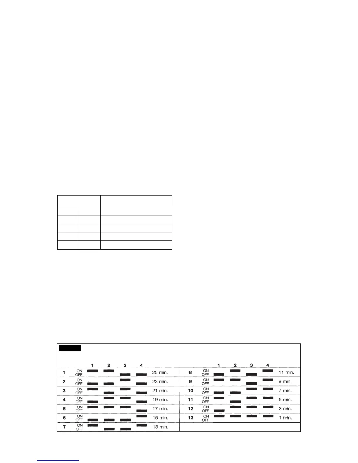
LENGTH OF TIMED PORTION OF FREEZING CYCLE ACCORDING TO THE
DIP SWITCH SETTING COMBINATIONS
TAB. B
size of the cubes (Large or Medium) as per the
following setting:
ON ON : PROGRAM A
ON OFF : PROGRAM B
OFF OFF : PROGRAM C
OFF ON : PROGRAM D
LENGTH OF HARVEST CYCLE
ACCORDING TO THE TIME TO DROP THE
EVAP. TEMPERATURE FROM 0°C TO -15°C
LENGTH PROGRAMS
HARVEST
CYCLE
ABCD
180” Up to 6’30” *** Up to 9’30” xxxx
165” 6’30”-7’ Up to 3’ 9’30”-10’ xxxx
150” 7’-8’ 3’-3’15’ 10’-11’ xxxx
135” 8’-9’ 3’15”-3’30” 11’-12’ xxxx
120” 9’-10’30” 3’30”-4’30” 12’-13’30” < 3'
105” 10’30”-12’ 4’30”-6’ 13’30”-15’ 3' - 4'
90” >12’ >6’ >15’ > 4'
The DIP SWITCH N° 7 and 8 allow the extention
of the length of the harvest/defrost cycle according
to their combination as per following chart:
DIP SWITCH ADDITIONAL DEFROST TIME
78
ON ON 0
OFF ON 30"
ON OFF 60"
OFF OFF WATER PUMP OFF
The 9th key is used to supply power to the water
pump for the first 15 seconds of the defrost cycle
- position OFF - or for the first 30 seconds -
position ON.
The 10th key is used to modify the CUT-OUT
condensing temperature from 70°C (160°F) for
the air cooled versions - ON position - to 60°C
(140°F) - OFF position - for the water cooled
versions.