Page 26
Page 26
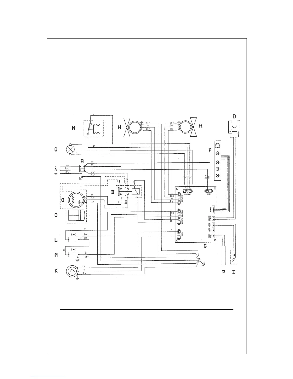
MV 12-21-32-50 - WIRING DIAGRAM
220 V. 50 Hz. 1 ph.
A - Input terminal board
B - Compressor contactor
C - Compressor
D - Ice sensor
E - End defrosting switch (two on MV 50)
F - Led card
G - Electronic card
H - Fan motor (one on MV 12 and MV 50)
K - Water pump
L - Water dischargue electrovalve
M - Gas electrovalve
N - Max pressure switch
O - Max pressure switch signal
P - Condenser temperature probe
Q - Heating resistance of carter compr.
(where used)
m = brown
bc = light blue
gv = yellow green
b = white
n = black
r = red