04
FRANÇAIS
DEUTSCH
05
ENGLISH
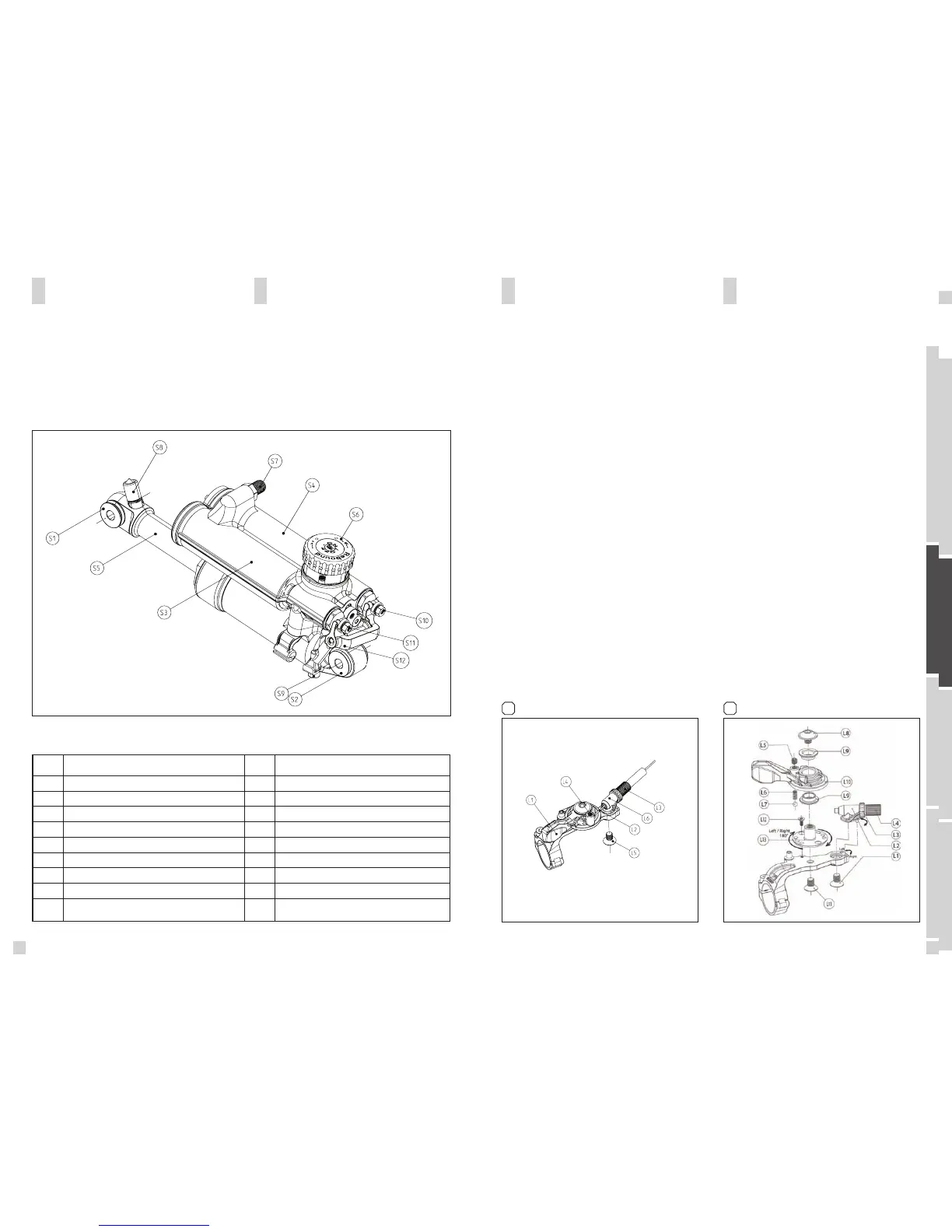
In the drawing of the shock and remote lever, shown
below, you will see the parts indicated with numbers
which will be used in the manual for the adjustment
and set-up.
EQUALIZER TC SHOCK AND
REMOTE CONTROL LEVER
BASIC SET-UP OF THE REMOTE
CONTROL OF EQUALIZER
TC SHOCK
1. Put the remote lever (L1) to position “lock-out”
2. Fix the remote control cable (L2) with the cable fixa-
tion screw (S9) using a 3mm allen key (tightening
torque: 3 Nm) on the Mode Lever (S12)
3. Put the remote lever now to position “Traction Mode”
The Lock Out Pin (S11) should be pulled out approx.
1mm.
4. When putting now the remote lever to position “All
Travel” the cable will pull the Mode Lever (S12) inclu-
ding the Traction Mode Pin (S10) and the shock will
offer now the full travel.
5. Check now the set-up for perfect function of remote
lever and shock
6. In case you want to fine-tune the brake-away power
of the remote lever, you can do this by using a 2mm
allen key and by turning the allen screw (L4). In case
you want to readjust the tension of the remote control
cable you can do this by using the tension screw (L3).
[1]
S1 Upper Shock Bolt
S2 Lower Shock Bolt
S3 Left Piggy-Back
S4 Right Piggy-Back
S5 Shock Piston
S6 Rebound Adjuster/Power Stabilizer Knob
S7 Positive Chamber Valve
S8 Negative Chamber Valve
S9 Remote Cable Fixation Screw
S10 Traction Mode Pin
S11 Lock Out Pin
S12 Mode Lever
L1 Remote Lever
L2 Remote Control Cable
L3 Tension Screw
L4 Allen Screw
L5 Allen Screw
L6 Cable Guide Hanger
1
MOUNT OF THE
REMOTE CONTROL
OF EQUALIZER TC SHOCK
To switch the TC2 Lever from one side of the bar to the
other one, please proceed as explained below:
[2] [3]
1. Remove the inner cable from the system as shown
in the Equalizer TC manual
2. Unscrew the clamp fixing screw on the bar clamp
with a 3 mm Allen key
3. Unscrew screw L1 by using a 3mm Allen key
4. Take the cable guide assembly (L2 + L3 + L4) away
5. Unscrew screw L5 with a 2 mm allen key
6. Unscrew the main screw L8 with a 4 mm allen key
7. Lift parts L8, L9 (2x) and L10 . Take the spri ng L6
and the ball L7 out of the assembly. Pay attention not
to loose them.
8. Remove screw L12 with 1.5mm allen key
9. Loosen base plate fixing screw L11 with a 3 mm
allen key
10. Turn index plate L13 to the position of your choice
(turn it of 180° for left or right position ), see detail
pictures.
2
 Loading...