06
FRANÇAIS
DEUTSCH
07
ENGLISH
IImmppoorrttaanntt:: RReemmoovvee tthhee ppuummpp bbeeffoorree
tteessttiinngg tthhee sshhoocckk..
The negative air chamber contains the air-spring
influencing the brake-away and characteristic while
absorbing shocks. A too high brake-away can cause
a non-secure and uncomfortable ride.
To adjust the air pressure of the negative chamber
of the Scott Equalizer TC Shock please refer to the
following instruction:
1. Remove the cap of the silver valve (S8) located on
the Shock Piston (S5)
2. Mount the shock pump with its adaptor on the valve
3. Pump the same pressure you have used for the
positive chamber into the negative chamber.
4. When you reached the needed pressure remove
the pump and put the valve cap on the valve.
We recommend making sure that the pressure
balance between positive and negative chamber
follows this manual.
Not doing so may cause a loss in performance or
comfort or may result in damage of the shock.
After adjusting positive and negative chamber
according to the rider’s weight you can double check
by using the SAG-Boy, which is on the back of the
manual, if the SAG (negative travel) is well adjusted.
The positive air chamber contains the air-spring you “sit-
on” while riding.
IImmppoorrttaanntt:: FFoorr aallll aaddjjuussttmmeennttss ooff
tthhee aaiirr sspprriinngg
tthhee rreemmoottee lleevveerr hhaass ttoo bbee iinn tthhee ““aallll ttrraavveell””
ppoossiittiioonn..
To adjust the air pressure of the positive chamber of the
Scott Equalizer TC Shock please refer to the following
instruction:
1. remove the valve cap of the black valve (S7) located
on the Left Piggy-Back (S3).
2. mount the shock pump with its adaptor on the valve
3. pump the recommended pressure into the shock. On
the inner side of the seatstays you will find a table sho-
wing in the black colored areas the recommended air
pressure of the positive chamber according to the rider’s
weight.
4. when you reached the needed pressure remove the
pump and put the valve cap on the valve
.
SET-UP OF POSITIVE AIR
CHAMBER EQUALIZER
TC SHOCK
SET-UP OF NEGATIVE AIR
CHAMBER EQUALIZER TC
SHOCK
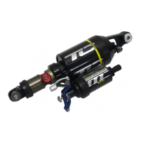
RECOMMENDED TOOLS FOR
THE SHOCK SET-UP
For the set-up of the shock we recommend to use
the tools listed below:
- a shock pump with a scale up to 30 bars/435 psi
with a special air valve connector preventing from
air getting away while removing the pump from
the shock valve, this will result in an exact air
pressure. Therefore we strongly recommend the
use of the Scott Shock Pump which is attached to
your bike
- the SAG-Boy on the back of this manual
3
11. Refix screw L12 with 3 Nm ( 27 in - lbs)
12. Refix screw L11 with 5Nm (44in - lbs)
13. Reassemble parts L8, L9 (2x) and L10 .
14. Tighten screw L8 with 5 N m (44in - lbs)
15. Insert the index ball L7 and the spring L6 in the
hole of the lever L10. Mak e sure that the ball fits
exactly in one of the 3 groves of index plate L13 (if
necessary, turn the lever L10 to reach one of these
positions)
16. Insert screw L5 (just tighten it until 2mm of its
thread are in the lever L10)
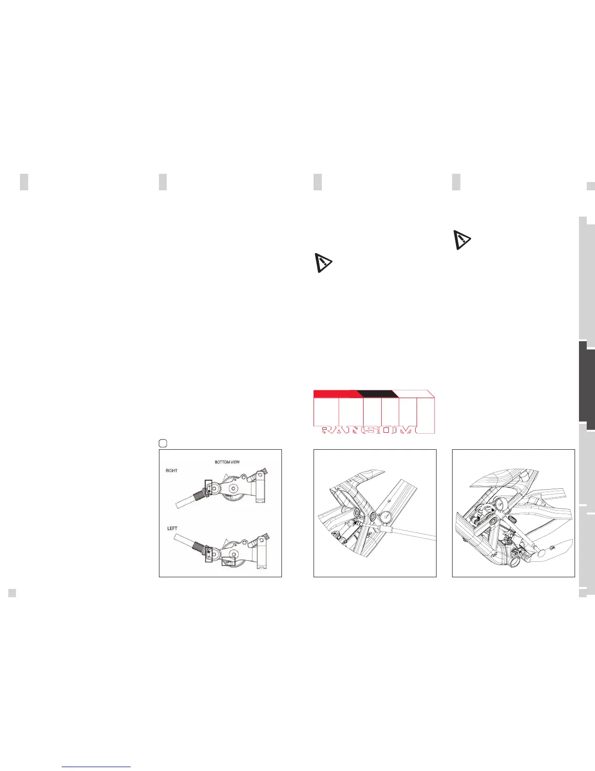
17. Position the cable guide assembly (L2+ L3 + L4) :
put the pin on the downside of L2 into the hole cor-
responding to the side of bar you want to put the lever
(see picture)
18. Tighten screw L1 with a tightening torque of 5Nm
(44in - lbs)
19. Double check the position of the lever parts in
combination to the bar - side by comparing the visible
side indication on the downside of index plate L13 as
shown on detail pictures (Bottom view).
20. Fix the lever on the bar by screwing the clamp
fixing screw of the lever clamp with 5 N m (44in - lbs)
21. Insert the cable
22. Fix the cable on your shock (see Equalizer TC
manual).
23. Adjust the index force of your lever by
screwing/unscrewing screw L5 until you reach the
break - away force of lever L10 of your choice.
MOUNT OF THE
REMOTE CONTROL
OF EQUALIZER TC SHOCK
 Loading...