EN ::: 26
EN
FR ::: 26
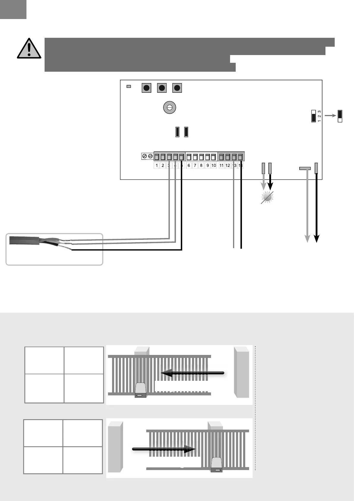
> MAKING THE KIT CONNECTIONS
Borne 13
MOT
Borne 14
MOT
black Red
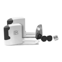
Connection of the motor according to opening direction of gate:
Diagram as seen from inside the property)
open at left
open at right
Borne 14
MOT
Borne 13
MOT
Red Black
Wires from limit switch.
Cut off the power supply (disconnect optional batteries) before making any modi cations.
Implementation, electrical connections and adjustments must be made in accordance
with good practice by a quali ed and specialized person.
If you have any doubts about the installation, seek advice !
2 blacks
red
Motor
red
Tip
If the motor fails to stop when the mechanical
switch is activated then the two red wires should be
inversed at terminals 8 and 9.
(solar option)
To solar panel
see page 33
or
(non-solar option)
to back-up battery
see page 33
(non-solar option)
to transformer
see page 25
Connection of the motor
according to opening
direction of gate:
Diagram as seen from
inside the property)
If the motors fails to turn in
the correct direction.
The wires at terminals
15 and 16 should be
inverted.
P2 P3P1
DL1
RV1
JP1
FS1FS2
- BATT+
24V
12V
BATT
FS4
FS3
JP2JP3
12V
24V
JP1