EN ::: 32
EN
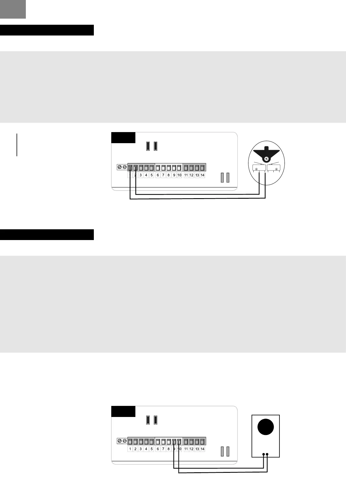
KEY SELECTOR
INSTALLATION :
1 - place the wires hole in the base.
2 - x the base to the wall using screws and plugs (not supplied).
3 - making connections: wires stripping and crimping lugs provided.
Insert the terminals into the legs of the switch.
4 - lift the front cover using the notch.
5 - attach the base and lock using the 2 screws provided.
6 - clip the front cover.
INFO
the key selector has
no polarity.
P2 P3P1
DL1
RV1
JP1
FS1FS2
- BATT+
24V
12V
BATT
FS4
FS3
CTR 58
JP2JP3
12V
24V
JP1
CTR58
key selector
C NO NC
NO
C
P2 P3P1
DL1
RV1
JP1
FS1FS2
- BATT+
24V
12V
BATT
FS4
FS3
CTR 58
JP2JP3
12V
24V
JP1
CTR58
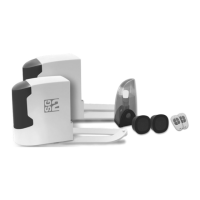
transponder
+
-
Power supply
12 V or 24 V
TRANPONDER
INSTALLATION :
1 - Fix the bottom of the transponder to the wished place Thanks to 2 lived supplied
2 - Connect(Bind) your transponder with your card. Electronics of automatism - Power supply12 or
24 V.
3 - Go directly in front of your electronic case.On the electronic board : Press on P1 and release.
The light DL1 ignites, goes out and Relight.
While DL1 ared up again, spend your 1st badge In front of the transponder.
4 - Repeat the operation N ° 3 entirely to program Following badges.
5 - Badges are programmed, you can open your gate.
6 - For cancel, maintain the support on P1 until the light DL1 goes out (approximately 10 seconds).
All the badgesare canceled.