TB-9017 Page 2 of 6
© 2015 DESCO INDUSTRIES, INC.
Employee Owned
SCS - 926 JR Industrial Drive, Sanford, NC 27332 • (919) 718-0000 • Website: StaticControl.com
Continuity Test: Place the Tester on a table top or
other stable surface and attach the leads as shown in
Figure . Place the test weights on the calibration plate
or other bare metal surface and plug in the test leads.
Set the main selector switch to CONTINUITY TEST.
Press TEST. The pointer should come to rest in the
green section of the CONTINUITY scale. If not, the
test leads may be defective or the weights may require
maintenance or cleaning.
Surface Test (Resistance Measurement): Refer
to the two following sections to determine which
measurement(s) should be used for your application.
Place the Tester on a table top or other stable surface
and attach the leads as shown in the appropriate sketch
gures 5-1 through 5-5. Set the Main Selector Switch
to the desired SURFACE TEST voltage. Place the test
weight(s) on the surface to be tested and connect the
test leads. Press TEST for 15 seconds and then read the
resistance from the OHMS scale. After all readings have
been completed, return the Main Selector Switch to the
OFF position.
Resistance Measurement of Static
Control Work Surfaces
This section provides a summary of the types of surface
measurements specied and described by ESD-S4.1.
Measurements are performed for three reasons:
1. Periodic performance testing of installed static
control work surfaces.
2. Qualication of installed static control work surfaces.
3. Evaluation of static control work surface materials.
Note: The following paragraphs are offered as
a condensed summary of the test methods and
procedures outlined in the EOS/ESD standard. For
complete details, refer to the standard.
Test Description
1. Periodic Performance Testing Of Installed Static
Control Surfaces: (Measurement of resistance from
the top of an installed surface to ESD GROUND
(RTS-ESDG) at ambient temperature and humidity).
Note: ESD GROUND is the point at which the ground
cord or other grounding conductor from the static
control surface is connected. The ground point may be
an electrical ground, building ground, or other suitable
ground. If you have questions concerning the correct
ground, refer to ANSI/ESD STANDARD S6.1 and/or
contact a qualied electrician.
This Resistance-to-Ground test veries the surface
is working correctly and will drain a static charge in a
reasonable time.
This test involves measurement of the total resistance
from the static control surface through the conductor or
ground cord to the ESD GROUND (ESDG), verifying the
static control system is functioning correctly.
Note: ESD-S4.1 suggests that a static control surface
that measures in the range of 1 x 10
6
ohms to 1 x 10
9
ohms.
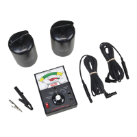
Figure 4. Periodic Preformace Tests of Installed
Surfaces.
The following procedures should be followed when
testing installed static control surfaces:
A. Complete BATTERY TEST and CONTINUITY TEST.
B. Set the SCS 701 Analog Surface Resistance
Megohmmeter Kit on a table top or other stable
surface and place a test weight at the desired test
point as shown in Figure 5. Connect the test leads
to the meter using the right angle banana plugs at
the meter. Then connect one of the test leads to the
test weight and the other to the ESD GROUND using
one of the supplied clips.
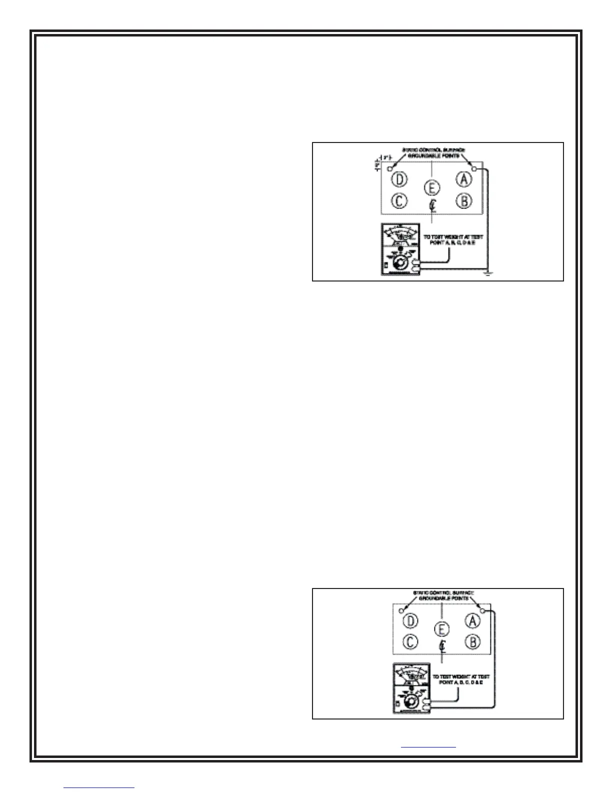
C. Test the static control surface using the 100 volts
SURFACE TEST. Press the TEST button for 15
seconds, allowing the pointer to stabilize; record the
readings for each test point. If the reading is below
1 x 10
6
ohms, check the static control surface for an
alternate path to ground; correct and retest. If some or
all the readings are above 1x10
9
ohms, the static
control surface may be dirty. Clean the surface using
the manufacturer’s recommended cleaning procedure.
If the resistance reading is “innite,” there is an
interruption (open) in the ground connection; repair
and retest.
Figure 5. Qualication Tests of Installed Surfaces.