TB-9017 Page 3 of 6
© 2015 DESCO INDUSTRIES, INC.
Employee Owned
SCS - 926 JR Industrial Drive, Sanford, NC 27332 • (919) 718-0000 • Website: StaticControl.com
2. Qualication of Installed Static Control Surfaces
[Measurement of resistance of the top surface to
the groundable point of the static control surface
(RTS-GP)]. GROUNDABLE POINT is the point
at which the grounding conductor is connected
to the static control surface; the GROUNDABLE
POINT is most commonly a snap (mats), a bolt
(laminate), or a strip of conductive foil tape (ooring).
This QUALIFICATION measurement is similar
to those described in the test description section
and is used to verify the correct installation of the
GROUNDABLE POINT by the manufacturer or by
the user. While the test procedure is the same, the
test setup is slightly different; see Figure 5.
3. Evaluation of Static Control Materials:
[Measurement of the resistance between two points
on top of a static control surface (RTS-TS), and the
resistance between a point on the surface and the
groundable point (RTS-GP)] Material measurements
are done to determine the intrinsic electrical
properties of static control work surface materials.
Note: Values obtained by these tests may not reect
how a material will perform when installed as a static
control surface.
Material evaluations are typically done at two
humidities (12% RH and 50% RH) to determine
whether the electrical properties of the material
are humidity-dependent. If the low humidity test
results are borderline or not within the expected
ranges, caution should be exercised when using
such materials in winter months or in dry conditions.
To assure test accuracy, a minimum of six samples
should be tested.
The test procedure is as follows:
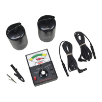
A. Prepare a minimum of six samples of each material
to be tested as shown in Figure 6.
B. Clean samples per manufacturers recommended
cleaning procedures. Condition samples at 73°F
(23° C) and 50% RH for 48-72 hours.
Note: Samples must be maintained at the appropriate
humidity level throughout the test procedures.
C. Complete BATTERY TEST and CONTINUITY TEST.
D. Surface-to-Groundable Point Test: Test samples
per Figure 7, using both the 100 volts and 10 volts
SURFACE TEST ranges at 50% RH and record the
values as (RTS-GP).
Figure 6. Material Evaluation Sample Conguration.
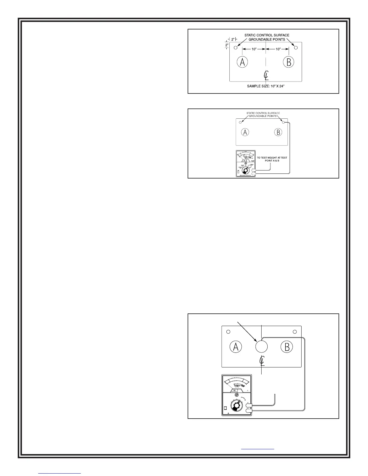
Figure 7. Material Evaluation Surface to Groundable
Point Test.
Procedure: Place the SCS 701 Analog Surface Resis-
tance Megohmmeter Kit on a table top or other stable
surface. Connect the test leads to the Tester by means
of the right angle banana plugs. Connect the other end
of one of the leads to one of the test weights and place
the weight on the surface to be tested. Use one of the
supplied clips to connect the other lead to the ground-
able point on the static control surface. Depress TEST
button for 15 seconds and then record the reading.
E. Surface-to-surface Test: Test samples as shown in
Figure 8 use both test weights and repeat the same
test procedure used to determine (RTS-GP).
F. Repeat A through E after conditioning samples at
73°F (23°C) and 12% RH. Use the same test points
and record the values.
OF F
10V
100V
BA TTE RY
TEST
CONTINUITY
TEST
TEST
READ MA NUAL BEFORE US E
OHMS
SURF AC E
TEST
TAUT BAN D
SUSPENSION
10
9
1G
10G
FAIL
PA
S
S
10
10
10
11
100G
10
8
10
7
10
6
10
5
0
1M
100K
0
10M
100M
CONTINUITY
BATTE RY
100V
0
10K
100K
1M
10M
100M
TO
TEST W EIGHT AT
TEST
POINT A & B
STATIC CONTROL SURFACE GROUNDABLE POINTS
Figure 8. Material Evaluation Surface to Surface Test.