SECURITY DOOR CONTROLS
www.sdcsecurity.com service@sdcsecurity.com
[t] 800.413.8783 805.494.0622 [f] 805.494.8861
801 Avenida Acaso, Camarillo CA 93012 • PO Box 3670, Camarillo CA 93011-3670
SECURITY DOOR CONTROLS
sdcsecurity.com service@sdcsecurity.com
© 2010 Security Door Controls Printed in the U.S.A. LIT-EZ Option Kit Upgrades 12.10
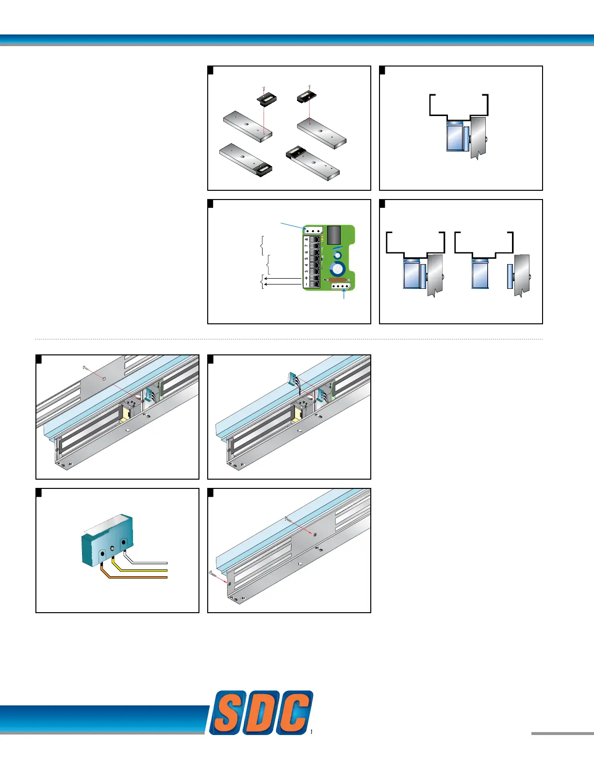
EZ-D-10-2: DOOR
POSITION SENSOR
Modular Kit
Indicates the door is open
and closed.
Application:
Door position status annunciation,
anti-tailgating, interlock, mantrap
and communicating bathroom
system logic.
Output: 2 Modules provided
SPDT Dry Contact, 250 mA
@ 12/24VDC
1
3 4
2
Input module wiring. Annunciation
Re-install armature per installation instructionsAttach door status module to each armature
Remove cover plate Replace cover plate
Place anti-tamper switch as shown.
Cover depresses switch
arm when mounted
Anti-tamper wiring
1 2
1
3 4
2
Input module wiring. Annunciation
Re-install armature per installation instructionsAttach door status module to each armature
Remove cover plate Replace cover plate
Place anti-tamper switch as shown.
Cover depresses switch
arm when mounted
Anti-tamper wiring
1 2
1
3 4
2
Input module wiring. Annunciation
Re-install armature per installation instructionsAttach door status module to each armature
Remove cover plate Replace cover plate
Place anti-tamper switch as shown.
Cover depresses switch
arm when mounted
Anti-tamper wiring
Com
No
NC
B Option
Connector
B Option
Magnetic Bond Sensor
D Option
Door Status Sensor
Magnetic Core
Connector
12 or 24 VDC
LOCKED - NO
COM
UNLOCKED - NC
CLOSED - NO
COM
OPEN - NC
Locked Unlocked
3 4
1
3 4
2
Input module wiring. Annunciation
Re-install armature per installation instructionsAttach door status module to each armature
Remove cover plate Replace cover plate
Place anti-tamper switch as shown.
Cover depresses switch
arm when mounted
Anti-tamper wiring
1 2
1
3 4
2
Input module wiring. Annunciation
Re-install armature per installation instructionsAttach door status module to each armature
Remove cover plate Replace cover plate
Place anti-tamper switch as shown.
Cover depresses switch
arm when mounted
Anti-tamper wiring
B Option
Connector
B Option
Magnetic Bond Sensor
D Option
Door Status Sensor
Magnetic Core
Connector
12 or 24 VDC
LOCKED - NO
COM
UNLOCKED - NC
CLOSED - NO
COM
OPEN - NC
3
2
1
3 4
2
Input module wiring. Annunciation
Re-install armature per installation instructionsAttach door status module to each armature
Remove cover plate Replace cover plate
Place anti-tamper switch as shown.
Cover depresses switch
arm when mounted
Anti-tamper wiring
Com
No
NC
B Option
Connector
B Option
Magnetic Bond Sensor
D Option
Door Status Sensor
Magnetic Core
Connector
12 or 24 VDC
LOCKED - NO
COM
UNLOCKED - NC
CLOSED - NO
COM
OPEN - NC
Locked Unlocked
3 4
1
3 4
2
Input module wiring. Annunciation
Re-install armature per installation instructionsAttach door status module to each armature
Remove cover plate Replace cover plate
Place anti-tamper switch as shown.
Cover depresses switch
arm when mounted
Anti-tamper wiring
Com
No
NC
B Option
Connector
B Option
Magnetic Bond Sensor
D Option
Door Status Sensor
Magnetic Core
Connector
12 or 24 VDC
LOCKED - NO
COM
UNLOCKED - NC
CLOSED - NO
COM
OPEN - NC
Locked Unlocked
4
EZ-A: ANTI-TAMPER
SWITCH - Modular Kit
Indicates cover plate removal
Output:
SPDT Dry Contact, 3 Amp @ 12/24VDC
1 only required