© 2007 Security Door Controls Printed in the U.S.A. LIT-Datasheet date qty vendor
SECURITY DOOR CONTROLS
www.sdcsecurity.com service@sdcsecurity.com
[t] 800.413.8783 805.494.0622 [f] 805.494.8861
801 Avenida Acaso, Camarillo CA 93012 • PO Box 3670, Camarillo CA 93011-3670
SECURITY DOOR CONTROLS
sdcsecurity.com service@sdcsecurity.com
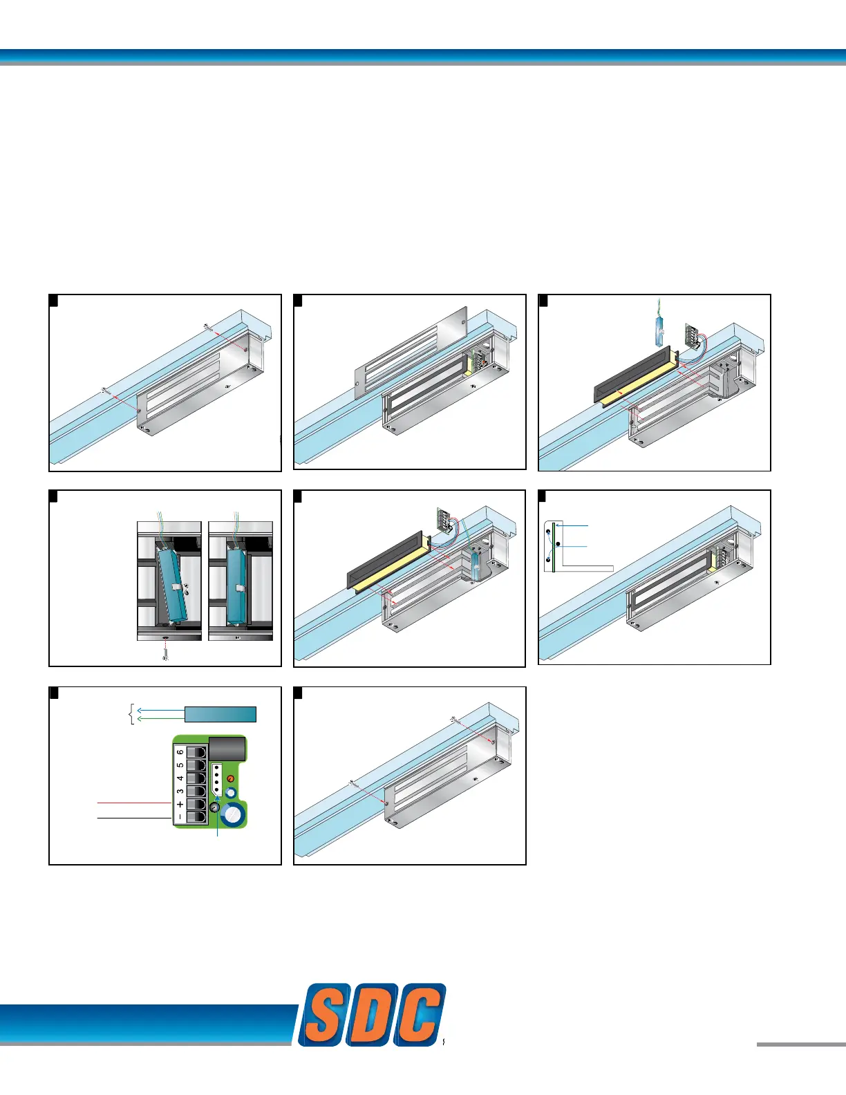
B Option
Magnetic Bond Sensor
NOT USED
POWER
DPS CO
NC
NO
Magnetic Core
Connector
{
NO
COM
Cradle
Position Posts
PC Board
Input module wiring.8
Remove cover plate screws.
1 2
Remove cover plate.
3
7
Lift input module
and magnetic coil
from the case.
4
Place input module vertically between post
at each side of case.
Remove 1 screw
from the case
bottom.
Place the
Magnetic Bond
Sensor at the
base of the
Magnetic Core.
Secure sensor
in place with
screw as
shown.
5
The Magnetic Bond Sensor
should be positioned as
shown below, after step 4.
9
Attach cover plate.
EZ-B-80 MAGNETIC BOND SENSOR
Modular Kit
B Option
Magnetic Bond Sensor
NOT USED
POWER
DPS CO
NC
NO
Magnetic Core
Connector
{
NO
COM
Cradle
Position Posts
PC Board
Input module wiring.8
Remove cover plate screws.
1 2
Remove cover plate.
3
7
Lift input module
and magnetic coil
from the case.
4
Place input module vertically between post
at each side of case.
Remove 1 screw
from the case
bottom.
Place the
Magnetic Bond
Sensor at the
base of the
Magnetic Core.
Secure sensor
in place with
screw as
shown.
5
The Magnetic Bond Sensor
should be positioned as
shown below, after step 4.
9
Attach cover plate.
4
Place input module vertically between post
at each side of case.
Remove 1 screw
from the case
bottom.
Place the
Magnetic Bond
Sensor at the
base of the
Magnetic Core.
Secure sensor
in place with
screw as
shown.
9
Attach cover plate.
B Option
Magnetic Bond Sensor
NOT USED
POWER
DPS CO
NC
NO
Magnetic Core
Connector
Cradle
Position Posts
PC Board
Input module wiring.8
Remove cover plate screws.
1 2
Remove cover plate.
3
7
Lift input module
and magnetic coil
from the case.
Place input module vertically between post
a
t each side of case.
Remove 1 screw
from the case
bottom.
Place the
Magnetic Bond
Sensor at the
base of the
Magnetic Core.
Secure sensor
in place with
screw as
shown.
5
The Magnetic Bond Sensor
should be positioned as
shown below, after step 4.
B Option
Magnetic Bond Sensor
NOT USED
POWER
DPS CO
NC
NO
Magnetic Core
Connector
{
NO
COM
Input module wiring.8
3
Lift input module
and magnetic coil
from the case.
4
Place input module vertically between post
at each side of case.
Remove 1 screw
from the case
bottom.
Place the
Magnetic Bond
Sensor at the
base of the
Magnetic Core.
Secure sensor
in place with
screw as
shown.
9
Attach cover plate.
B Option
Magnetic Bond Sensor
NOT USED
POWER
DPS CO
NC
NO
Magnetic Core
Connector
{
NO
COM
Input module wiring.8
3
Lift input module
and magnetic coil
from the case.
4
Place input module vertically between post
at each side of case.
Remove 1 screw
from the case
bottom.
Place the
Magnetic Bond
Sensor at the
base of the
Magnetic Core.
Secure sensor
in place with
screw as
shown.
9
Attach cover plate.
While a Door Status Sensor indicates the door is open
or closed, SDC’s Magnetic Bond Sensor provides higher
security monitoring by indicating the locked / unlocked
mode, tampering and low holding force. The use of
both the door status and magnetic bond sensor is
recommended for high security applications.
Application: Lock secure status annunciation,
mantrap system logic,
CCTV camera activation.
Output: SPDT Dry Contact,
250 mA @ 12/24VDC
 Loading...