18
Aligning the Hall sensor and magnets
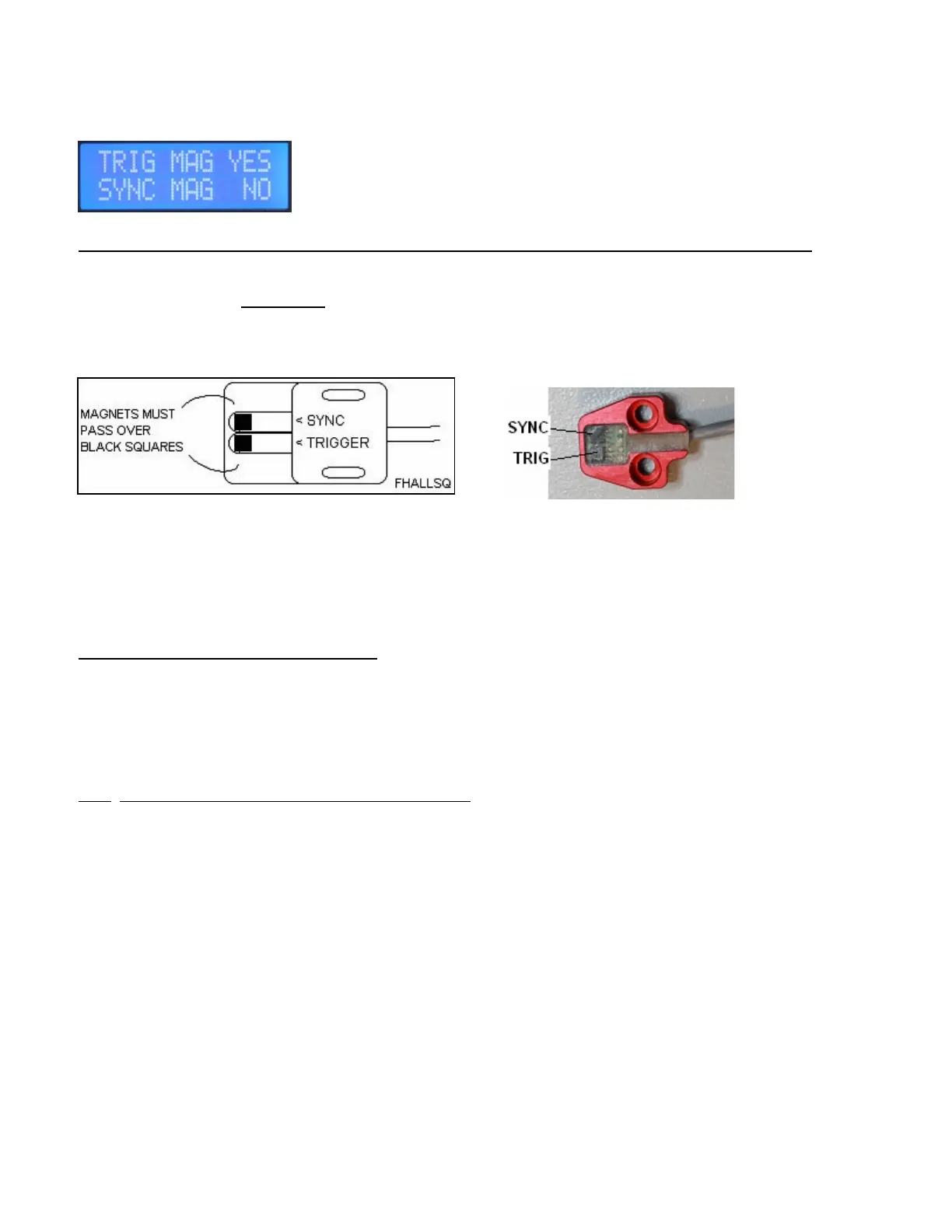
MAGNET SEEN WINDOW
Safety note, Disable power to coil pack(s) before doing hall alignment or checking.
Rotate the crankshaft very slowly by hand using appropriate tools.
LCD display, top line is used for checking trigger magnets. Bottom line is used for checking the sync magnet.
If CNC supplied brackets are used with the system, alignment is not adjustable but it is still required to verify that all
the magnets are being seen by the sensor, so the ignition will operate properly. Watch for magnets installed
backward which will then trigger the wrong sensor element in the hall sensor.
If the slotted type sensor is used then you will have to move the sensor inward or outward for best alignment to the
magnets.
Alignment Steps for slotted type sensor:
1. Best to rotate the crankshaft so that a trigger magnet is closest to the sensor.
2. Have the mounting bolts loosened slightly and slide the sensor in or out until the window shows TRIG YES. YES
means the CPi is seeing the trigger magnet.
3. On adjustable sensors, slide the sensor back and forth and try to find the mid-point where the Trig shows YES.
4. Tighten the hall sensor mounting bolts. Check remaining trigger magnets and also the sync magnet.
Each magnet should be seen for at least 2 to 3 degrees of crank rotation.
Note: This window has no use once the engine is running, since the sampling rate of the programmer is only about
twice per second. You will see NO in the display when running with the rare occasional flicker of YES for a magnet
being seen while software happens to be updating screen data when the magnet is over the sensor.
 Loading...