24
Apply heat shrink tubing so it extends over braid junction by about 3/16 inch. Shrink the tubing with a
heat gun and label each cable.
DB25 Main harness Terminations
Black 20 gauge (computer ground). Ground to aircraft structure or ground strip close to the EM-6.
Important! Makes sure this connection is good and strain relief this wire also.
Red 20 gauge ECU power. Switched 12V. Fused with 2 Amp fuse.
Important! Makes sure this connection is good.
Knob cable Strip length for cable sheath about 1 inch.
Knob Cable Singe ECU and 4cyl Dual ECU systems, Primary DB25 harness, crimp on mate n lok
terminals use pos #2 on the crimp tool. Orange stripe wire goes into position 1 in the mate n lok
connector housing. All white to position 2 middle. Blue stripe to position 3. If 4cyl dual ecu, the Backup
DB25 harness does not connect to the knob so there will not be a knob cable on the backup harness.
Knob Cable Dual ECU 6cyl systems, Primary DB25 harness and also the Backup DB25 harness crimp
on Mate-n-lok male terminals onto all 6 wires using #2 on the crimp tool.
Insert terminals as follows: Knob relay box 6cyl Dual ECU only
Orange stripe to Mate-n-lok pin1
All white to Mate-n-lok pin2
Blue stripe to Mate-n-lok pin3
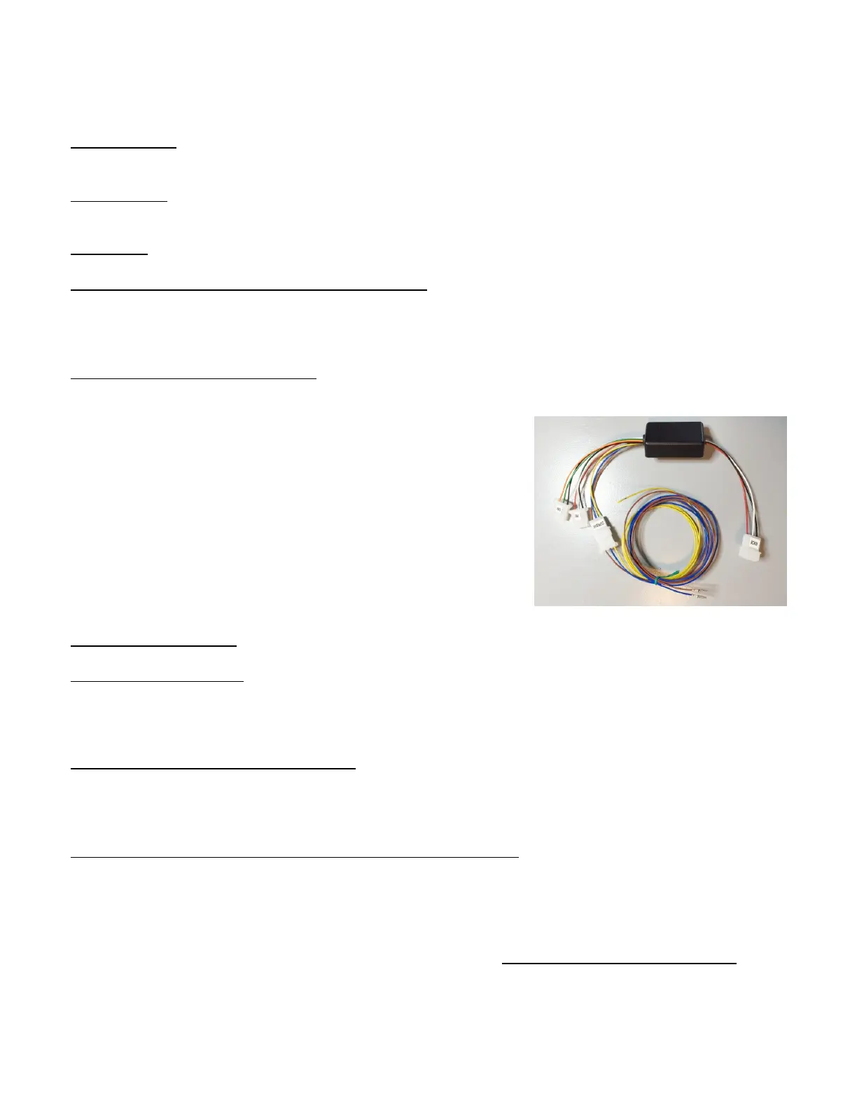
Locate the Knob relay box which is a small black 2”x 1” x 0.5”
enclosure with several wires and connectors. The Knob cables
from Pri and Bak DB25 harnesses plug into the Knobrelaybox as
marked on its connectors. The Knob relay box has a connector
labeled Knob which you plug into the mixture knob
potentiometer’s mate-n-lok plug. Other connections to the Knob
relay are covered below in the manual.
Green 20 gauge, pin 12: This supplies a 5V tach signal output to your tach or EIS.
Yellow 20 gauge, pin 22: This supplies a 12V tach signal output to your tach or EIS.
Tach signals are 2 pulses per crank rev on 4 cylinder engines, 3 pulses on 6 cylinder, 4 pulses on 8
cylinder.
Blue 20 gauge, pin 13 Main 25 pin D Sub: If you have the 3-1/8” programmer and are wanting to run LOP
then this wire needs to go to your LOP switch. Your other switch wire needs to go to +12V. When the
switch is turned On, the LOP will be activated, fuel will lean and timing advanced according to
programmed values.
Gray 20 gauge and O2 sensor or Wideband meter hookup, pin 24
On the SDS main harness there is a single gray 20 gauge wire which you can connect to a wideband O2
sensor controller. Connection is required when you want to display the AFR (air/fuel ratio) in the SDS
programmer or use Closed loop and Lean Warning functions in the SDS computer. The SDS can run
without an O2 sensor if this is desired but a wideband should be used to accurately tune the system.
Recommended Wideband O2 air/fuel sensor & controller is the Ballenger Motorsports AFR500 V2
options to select are the NTK Production grade sensor, and harness length of 7, 13 or 24ft.
AFR500 V2 Hookup to SDS is as follows:
Wideband Red to switched 12V through 5A breaker or fuse.
 Loading...