25
Wideband Black to ground buss or chassis ground.
Wideband Yellow to SDS main harness gray wire.
Wideband Black with white stripe connects to same place as SDS ECU pin 18 ground wire.
Mounting the O2 sensor, mount sensor minimum 12 inches from the exhaust port, and minimum 12
inches from exhaust tip (atmosphere). Sensor may overheat too close to port, and may pickup air when
too close to exhaust tip.
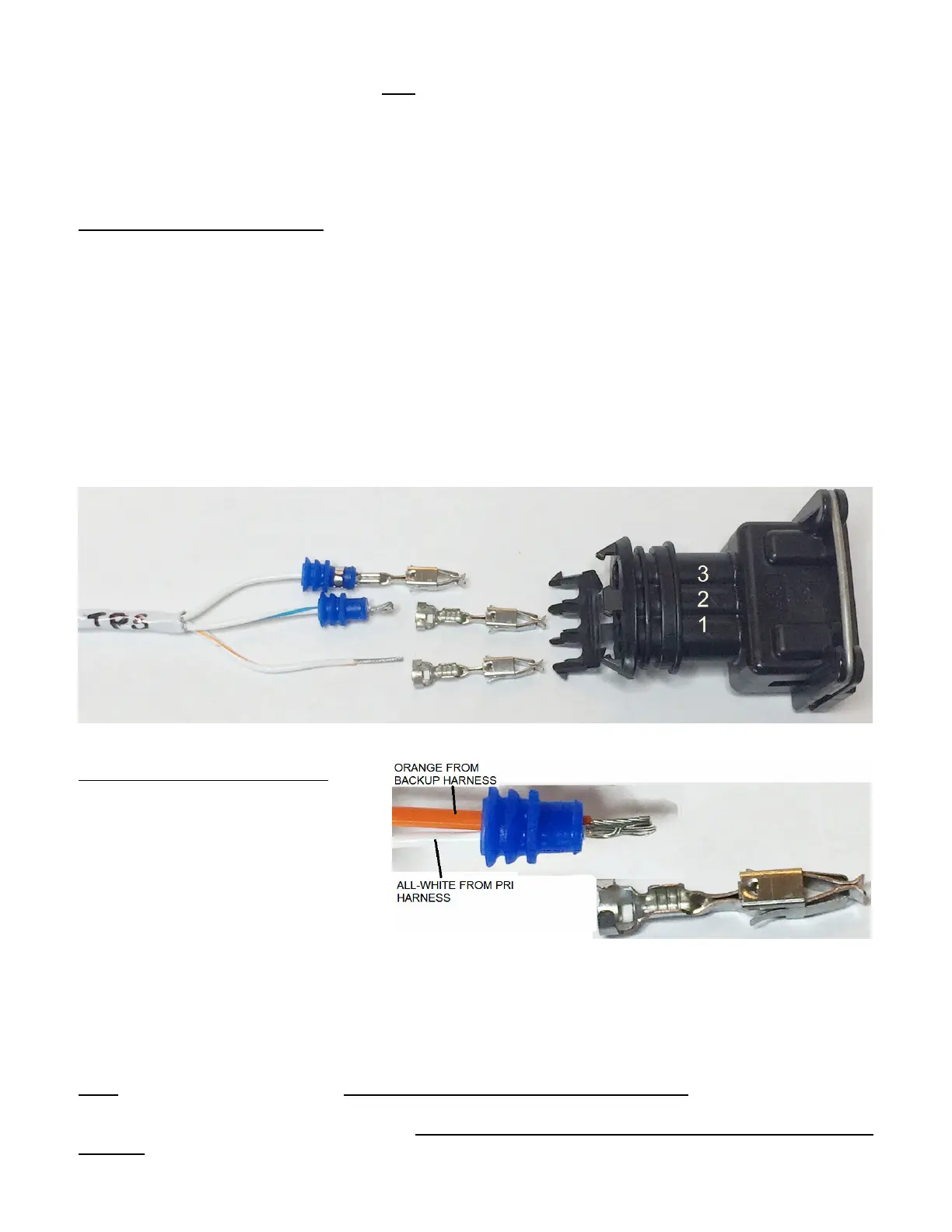
TPS Cable 4 Cylinder Dual ECU (throttle position sensor signal) On dual ECU 4cyl systems you will only
connect the TPS to the Primary ECU while the backup ECU will not need any connection to the TPS.
Strip about 1.5” of cable sheath, then strip length on each wire should be about 3/8” then fold the wire
over to double its size for better crimp results. Squeeze crimper hard using position #2. To crimp the
seal section of the terminal use position #1 on the crimp tool.
Be careful with these terminals going into the correct position, they are incredibly difficult to extract. If you
make a mistake its better to cut/solder/heatshrink wires instead of attempting extraction.
Note connector orientation in photo and numbers, insert wires as follows:
Orange stripe into #1 position.
Blue stripe into #2 position.
All white into #3 position.
Zip tie the TPS cable as close as possible to the connector so that it does not flop around.
Photo showing strip length terminals and TPS connector.
TPS Cable 6 Cylinder Dual ECU: TPS
cable from DB25 Primary harness,
Strip about 1.5” off the sheath. Locate
the all white wire, strip about 3/16” from
it. On the Backup DB25 main harness
locate the 20ga orange wire, strip
3/16”. Feed the Pri all white and Bak
orange through a blue seal then line
them up together. To lower stress on
this smaller gauge white wire, lay both wires into the crimp section of the terminal with the white wire at
the bottom and orange wire on top. Squeeze hard using #2 position of the crimper. As an option, you
can crimp a short piece of wire into the TPS signal pin and make another connection which can be more
easily disconnected with the white connectors and pins provided. To crimp the seal section of the
terminal use position #5 first, then #1 on the crimp tool, no need to squeeze hard just close up the gap is
good enough.
COIL cable, will be on the harness only on systems controlling ignition coil packs. 4cyl will have a 2
conductor cable, 6cyl a 3 conductor cable. 8cyl will have 4 separate 20 ga wires. These go to coilpack
signal inputs to trigger spark in the coilpack. Fuel Only systems will not have this cable on the DB25 main
harness.
 Loading...