Fig. 27
± 10°
1
2
5. MOUNTING OF THE RELEASE
For the Field there are foreseen two types of release:
RELEASE (with personalised key) and RELEASE PLUS
(with DIN key).
RELEASE
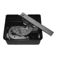
5.1. Grease the hinge (A) and mount the release system
under the leaf device using the 4 furnished screws (Fig. 22)
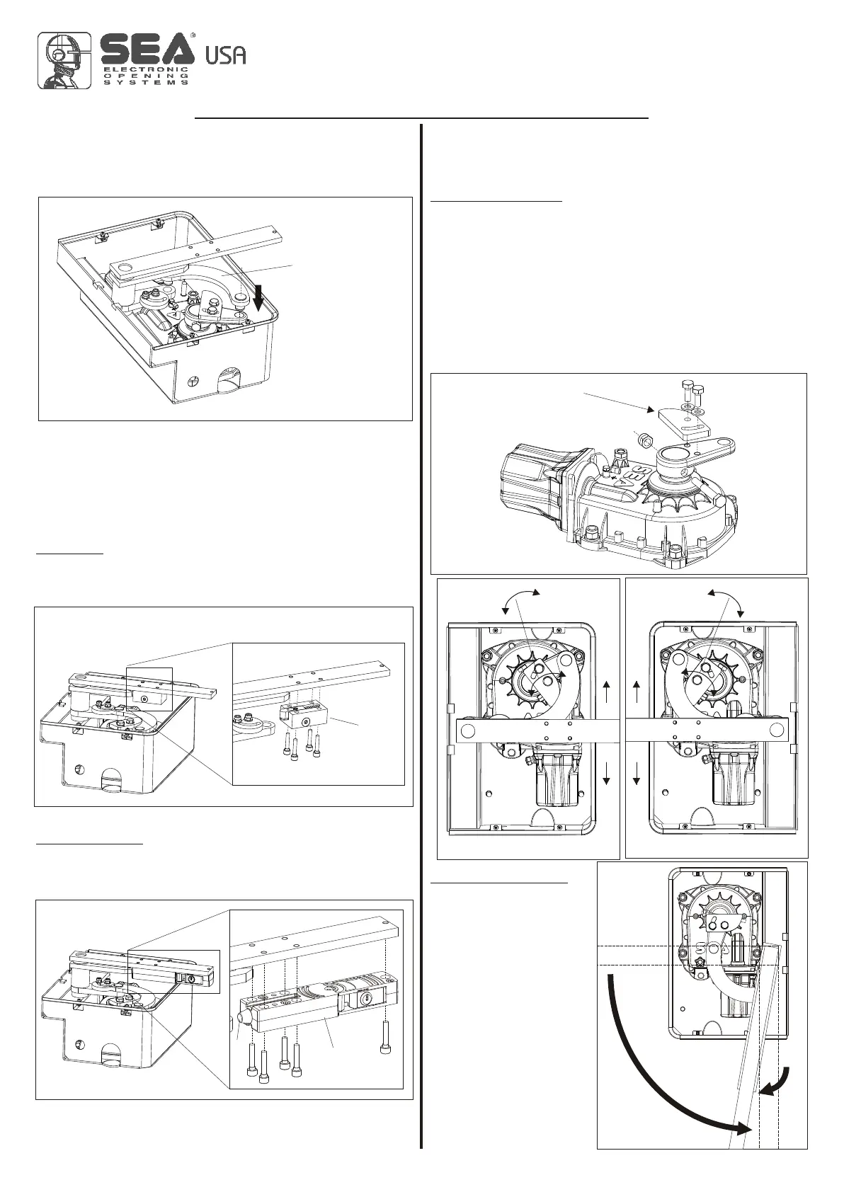
4.3. Connect the handle bar device to the motor using the
counter-connecting rod through the special holes.
Note: Grease very well the holes and respect the direction of
insertion of the counter-connecting rod (Fig. 21).
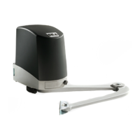
RELEASE PLUS
5.2. Grease the hinge (A) and mount the release system
under the leaf device using the 5 furnished screws (Fig. 23)
Carry out the electrical connections to the control unit as
described in the instructions supplied with SEA control unit.
Fig. 21
Connecting
rod
Fig. 22
Release
Fig. 23
A
Release
Plus
6. LIMIT SWITCH ADJUSTMENT
For the limit switch adjustment in closing and in opening
execute the following operations:
Limit switch in closing
Even if in closing there are limit switch stops mounted on the
ground it is necessary to adjust the limit switch of the Field,
operate as follows:
6.1. Close the leaves completely
6.2. Mount the cam of the limit switch as shown in Fig. 24, bring it
to the stop with the connecting rod and fix it with the special
screws.
The mounting of the cam and its adjustment is shown in Fig.
25 and 26.
6.3. Adjustable limit switches in closing ( from 85° to 95°
degrees)
Limit switch in opening
It is recommended to
have limit switch stops on
the ground in opening, if
already installed, it is not
necessary to adjust the
limit switches present on
the Field.
If there are no limit switch
stops in opening on the
ground, operate as
follows:
6.3. Open the leaves
completely (1) and bring
them back of about 10° (2)
(Fig. 27).
Fig. 24
Adjustable cam
of limit switch in closing
Fig. 25
+
-
Fig. 26
+
-
STOP CLOSING STOP CLOSING
+
-
+
-
LEFT RIGHT
International registered trademark n. 2.777.971
MECHANICAL INSTALLATION
FIELD
67410825 Rev.04 - 02/2016
9