SEA S.r.l. Zona Ind.le S. Atto – Teramo – Italia
Sito Internet: http://www.seateam.com
E-mail: seacom@rgn.it (Uff. Commerciale) seatec@rgn.it (Uff. Tecnico)
Cod. 67410170 Rev. 02 , 06/2001 Pag. 2 di 4
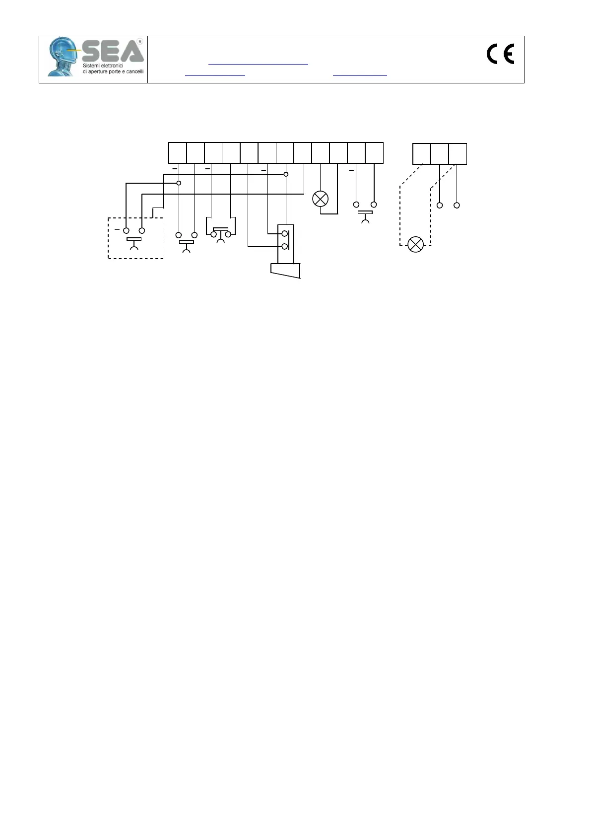
ELECTRICAL CONNECTIONS
1 – MAIN TERMINAL CONNECTION BLOCK (CN3 / CN6)
Fig. 2
N.B. Terminals 3 & 4 (Stop) and 5 & 6 (Safety) are normally closed inputs. These terminals must be
wire linked if a stop button or photocell is not being used.
2 - BLADE TYPE MAINS EARTH CONNECTION (FST1)
To be connected to the incoming mains earth. This connection provides an earth for the double sided earth
barrier tracks that are situated between mains and low voltage tracks.
MPU/EO FUNCTION DESCRIPTION
The MPU/EO control unit has been designed to automate residential sliding gates up to 4 metres in length with
a maximum weight of 400 Kg. The gate must run freely and not have any side to side play. It must also have
open and close physical travel stops fitted before the automation is carried out. Plan the cabling requirements
before installing the foundation plate. Leaving a spare cable duct into the unit can often be helpful. Mains and
low voltage cables should be run separately.
1. Electronic brake adjustment
The electronic braking action can be adjusted to give either a slow/soft or rapid/hard stop to the gate
movement by adjusting Trimmer TR2 (Fig. 3). The electronic braking action is started by the proximity limit
switch registering the presence of the limit plate.
2. Electronic reverse device
The friction clutch is located on the top of the motor and should be adjusted as lightly as practical, the
maximum force recommended to be exerted at the leading edge of the gate is 15 Kg. The emergency
release key can be used to adjust the clutch. If the gate is obstructed when closing, the obstacle is detected
by the motor revolution counter and the gate is stopped and reversed. If an obstacle is detected when the
gate is opening, the gate is stopped. The electronic reverse device is activated by the slipping action of the
friction clutch that is coupled to the electric motor. The clutch should be adjusted so to be allowed to slip
when the gate comes into contact with minimal obstruction. To decrease the clutch pressure, turn the
adjusting screw anti-clockwise; to increase the clutch pressure, turn the adjusting screw in a clockwise
direction. The clutch pressure must always be adjusted in every instance to take into account the weight and
running condition of the gate being automated. The pressure must never be excessive.
PHOTOCELL SAFETY IS RECOMMENDED FOR ALL SLIDING GATE LOGIC SELECTIONS
3. Logic
Logic is selected by DIP2. With DIP2 = OFF, Semi-automatic or push to open/push to close logic is selected.
DIP2 = ON selects Automatic logic and adjusts the pause before closing time (5-120 s.).
A Pedestrian opening input is available on terminals 10 and 11 if required.
SETTING UP THE GATE STOPPING POSITION
Only tack weld the Limit Place to rack while setting up. A gap of 5-8 mm. is required between the Limit Plate
and Limit Switch. The Limit Switch is located on the side of the casing directly above the pinion. The Limit
Indicator
lamp
24Vdc
3W MAX
Pedestrian
Start pulse
(NO)
 Loading...