2
page
FEATURES
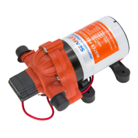
High Capacity Macerator and Bowl Scavenger Pump
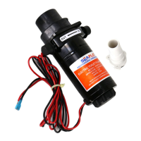
Flexible Impeller Flush Pump
Fully Enclosed, with Stainless Steel Shaft
Simply Operate by Pushing Button Switch
All Corrosion Resistant Materials for Marine Use
Thru Flow Approx. 1-1/2 Qts. per 5 Seconds of Operation
INSTALLATIONINSTRUCTIONS
Make sure inlet and outlet seacocks are all open; push switch button to operate. Operate until
bowl is completely flushed and discharge pump has scavenged water from bottom of bowl.
The SEAFLO electric marine toilet will provide 1 year of trouble free service if properly used. It will
handle waste and toilet tissue. It will not handle rags, sanitary napkins or hard solid objects.
Clean toilet with mild non-abrasive cleaners without strong aromatics. Cleaners having high
concentrations of aromatics, such as pine cleaners and strongly scented degrease concentrates,
can cause the pump's impeller to swell and possibly bind up.
If bowl does not pump out and begins to fill, partially close inlet valve until bowl is cleared and
completely pumped out. Then operate for a few seconds with both valves open to clear entire
toilet and discharge system. For maximum safety, when toilet is not in use or vessel is unattended,
close both the inlet and discharge seacocks.
To drain for winter layup, close inlet valve and operate for a few seconds until all water is pumped
out.
1
page
OPERATINGINSTRUCTIONS
SFMTP1-01 12 Volt SFMTP2-01 24 Volt
MODEL
APPLICATION
The SEAFLO electric toilet may be installed above or below the waterline. Flush pump is self-
priming with a vertical lift up to 4 feet; discharge macerator pump can operate against a vertical
head up to 4 feet.
SEAFLO flush pump can be used to convert the Raritan PH or Compact, Wilcox-Crittenden “Head
Mate”, Groco HC, Brydon No. 9127, 9128, or No. 59128 and virtually any other model marine
toilet using the “standard” bowl config-uration with a 3-3/4" diameter bolt circle, 4 hole pattern
in the base. Check the dimensional drawing to be sure the bowl will fit the flange dimensions as
shown.
PLUMBING CONNECTIONS
Connect inlet hose using either 5/8" or 3/4" ID hose (a sleeve is included to adapt pump inlet from
5/8" to 3/4"). Make sure all inlet connections are airtight and free of sharp bends or restrictions.
!
NOTICE: The toilet inlet must not be connected to a pressurized water
system.
Connect 1" or 1-1/2" hose to discharge port, and make suitable connection to holding tank or
other discharge system. Avoid sharp bends or restrictions. If the toilet is, or can be, below
waterline at any normal (including static) attitude of vessel heel and/or trim, a 3/4" Vented Loop
Fitting must be installed in the length of hose connecting the flushing pump to the inlet seacock.
The Vented Loop Fitting must be positioned so it remains slightly* above the waterline at all angles
of heel and trim.
*Recommended minimum height above waterline is 6".
For above waterline installations, a check valve may have to be installed in the flush water intake
line to ensure rapid pump priming. To retain water in bowl, make a loop in the discharge line about 8
inches above base of bowl.
DO NOT CONNECT INLET HOSE TO A PRESSURIZED PORTION OF THE
WATER SYSTEM.
ELECTRICAL CONNECTIONS
Select a location for the switch and instruction plate, making sure wire leads from both the toilet and power
source can be routed to the switch. Ensure the panel where installing switch is no more than 1" thick. Drill a
5/8" mounting hole and install switch and instruction plate. Use stranded copper wire of the correct size
(determined from the electrical specifications chart) to connect one side of the switch to the positive power
source.
NOTICE: Correct wire size and secure wire connections are very important. Undersized wire and unsecured
or corroded wire connections will cause a reduction in pump performance and possible pump failure. An
appropriate size fuse or equivalent circuit breaker (determined from electrical specications chart)
must be installed in the positive power lead within seven inches of the power source or in the
electrical power distribution breaker /fuse panel. Connect the other side of the switch to the orange
(positive) motor lead. Connect the black (negative) motor lead to the negative side of the battery or grounded
buss bar.
NOTICE: Correct motor polarity (red to positive, black to negative) is important. Reverse polarity
can damage motor and void warranty. Full voltage at the motor is required to properly operate
SEAFLO Electric Toilet. The toilet must be wired in a circuit independent of all other accessories.
 Loading...