4
page
3
page
ELECTRICALSPECIFICATIONS
25'-40'
#8
#10
15'-25'
#10
#12
10'-15'
#10
#14
0'-10'
#12
#16
SIZE
20
15
DRAW
20
10
VOLTAGE
12
24
AMP FUSE WIRE SIZE PER FEET OF RUN
Length of run is total distance from power source to product and back to ground.
40'-60'
#6
#10
DISASSEMBLY
Disconnect pump inlet and discharge hoses. Remove four screws, Key No. 11, pull out complete
motor, pump and macerator assembly. Remove macerator housing from base.
Remove discharge port, and inspect joker valve. Unscrew chopper plate lock nut, Key No. 10, by
turning counterclockwise, facing plate and remove chopper. Prevent shaft from turning by
inserting a screw-driver in slot of shaft protruding from rear of motor. Loosen centrifugal impeller
set screw and slide impeller off motor shaft.
Remove four flat head screws, wearplate, Key No.10, shaft sealing sleeve, gasket, Key No. 4; then
slide pump assembly off motor shaft. Replace all worn or damaged parts, clean remaining prts.
REASSEMBLYINSTRUCTIONS
Press seal into body with lip facing impeller; be careful not to cock seal in bore. Install pump body
on motor and position on register; lubricate impeller bore with pump grease. Install impeller,
gasket and wearplate. Make sure gasket surfaces are clean and smooth. Tighten wearplate
screws. Slide shaft sealing sleeve onto shaft and seat in its bore in wearplate. Relocate
centrifugal impeller about 1/8” from wearplate and secure with set screw. Position macerator
housing around centrifugal impeller then put chopper plate on end of shaft and secure with lock
nut. Install O-ring in O-ring groove in wearplate surface (a little grease will help hold in place).
Aligning key on top of macerator housing with slot in base, slide macerator assembly into base.
Secure pump assembly with the four screws.
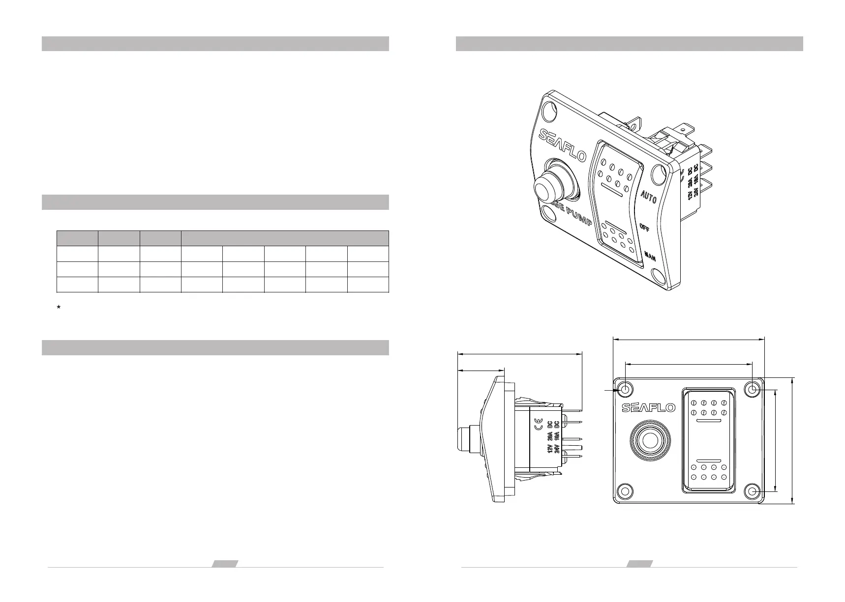
2.95" 75mm
2.52" 64mm
2.48" 63mm
2.0" 51mm
2.44" 62mm
0.91"23mm
SWITCHCONNECTIONDRAWRING
∅0.16" 4.0mm
 Loading...