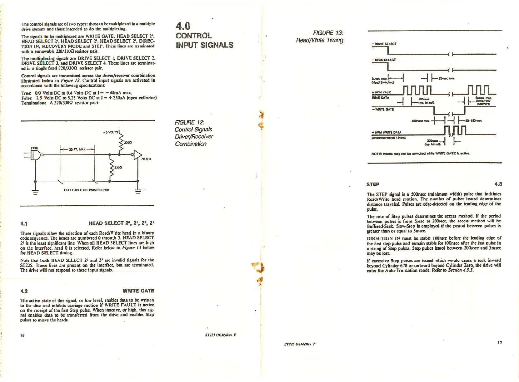
These signals allow the selection of each ReadfV'rite head in a binary
code sequence. The heads are numbered 0 throu)J J. HEAD SELECT
2° is the least significant line. When aU HEAD ~.ELECT lines are high
on the interface. head 0 is selected. Refer below to Figure 1J below
for HEAD SELECT timing.
Note that bolh HEAD SELECT 2' and
25 arc invalid signals for the
ST22S. These lines art present on the interface, but are tenninated.
The drive will not respond to these input signals.
The control sienals are of two types: those to be multiplexed in a multiple
drive systenn and those intended to do the multiplexine.
The signals co be multiplexed are WRITE GATE. HEAD SELECT 2·,
HEAD SELECT 2', HEAD SELECT 2', HEAD SELECT 2', DIREC-
TION IN. RECOVERY MODE and STEP. These lines are terminated
with a removable
22O/JJoQ resistor pair.
The multiple,ung signals arc DRIVE SELECT I, DRIVE SELECT 2,
DRIVE SELECT J. and DRIVE SELECT 4. These lines arc tenninat-
ed in a sinsl~ fixed 220/JJOQ resistor pair .
Control sigmals are transmitted across the driver/receiver combination
iUustrated below in Figure 12. Control input signals arc activated in
accordance with the following specifications:
True: 0.0 Volts DC to 0.4 Volts DC at I - - 48mA max.
False:
2.S Volts DC to S.2S Volts DC at 1- +2S~A (open collector)
Tenninatlol1O: A 220133012 resistor pack
The STEP signal is a SOOnsec(minimum width) pulse that intitiates
Read/Write head motion. The number of pulses issued detennines
distance traveled. Pulses are edge-detec:tedon the leadins edge of the
pulse.
The rate of Step pulses determines the access method. If the period
between pulses is from 5,isec to 2~. the access method will be
Buffcred-Seek. Slow-Step is employed if the period between pulses is
greater than or equal to Jmsec.
DIRECTION IN must be stable
1000sec before the leading edge of
the first step pulse and remain stable for iOOnsecal\er the last pulse in
a string of Step pulses. Step pulses issued between 2()(4isecand 3msec
may be lost.
If excessive Step pl:ises are issued which would cause
II seek inward
beyond Cylinder 670 or outward beyoDdCylinder Zero, the drive will
enter the Auto-Tru1cation mode. Refer
10 Section 4.J.J.
4.3
NOTE: HudlIIIIY not be awItched _ WRITE GATE .-.
-_SELECT
~ j-,---
- HEADSEL£CT
--, f -f ---
•..---t:---I -11--_.
~ SwIIdIongI
+MFMVAUD ~
REAODATA -I 1-- -11-"'-'--'
-WRITE GATE l1YP.bIIL ~ i=
---.-H ~ I-5G-J-
+ W'M WRITE DATA nJlfl------
_led J2rM«I _ I I-
11YP.11I ••••-,
STEP
FIGURE 13:
ReadfWrite Timing
'I
l
.-
of'
"j>
o/j
,,'
~I
480
CONTROL
INPUT SIGNALS
FIGURE 12:
Control Signals
DriverjReceiver
Combination
WRITE GATE
HEAD SELECT 20, 21, 22, 2J
FLAT CABlE OR TWISTED PAIR
4.1
4.2
The active state of this signal. or low level, enables data to be written
to the disc and inhibits carriage motion if WRITE FAULT is active
on the receipt of the first Step pulse. When inactive, Dr high, this sig-
nal enables data to be transferred from the drive and enables Step
pulses to mo"e the heads.
16
ml' OEM/Rn. F
m1' OEM/Mn. F
17
 Loading...


