2. INTRODUCTION
Heavy-duty frame provides full protection and incorporates carry handles for portability. Inverter generator suitable for running sensitive
electricalequipment.ProducesacleanACcurrenttomatchtheload.Longrunningtimeofupto8hoursonafulltankoffuel.Fittedwithtwo
230V13Ampsockets.Increasedfuelefciencycomparedtostandardgenerators.Featuresoilwarninglight,overloadindicatorandsight
glass to monitor fuel level.
3. SPECIFICATION
Model No ................................GI2300.........................GI3500
Motor Power ...........................2.3KW...........................3.5KW
Motor Type ................4-StrokePetrol..............4-StrokePetrol
Output .............................230V-50Hz....................230V-50Hz
Current Rating ...........................8.3A.............................15.2A
Continuous Power Rating......2000W...........................3200W
Max. Power Rating ................ 2300W...........................3500W
Fuel Tank Capacity ................... 13ltr................................13ltr
Max. Running Time ................. 13Hr..................................8hr
Noise Rating ...................... 95dB(A)..........................95dB(A)
Noise pressure level ............... 74db................................74db
Dry Weight .......................... 35.1Kg............................35.5Kg
Dimension (WxDxH) ... 440x520x470mm......440x520x470mm
Fuel ....................... Unleaded Petrol..............Unleaded Petrol
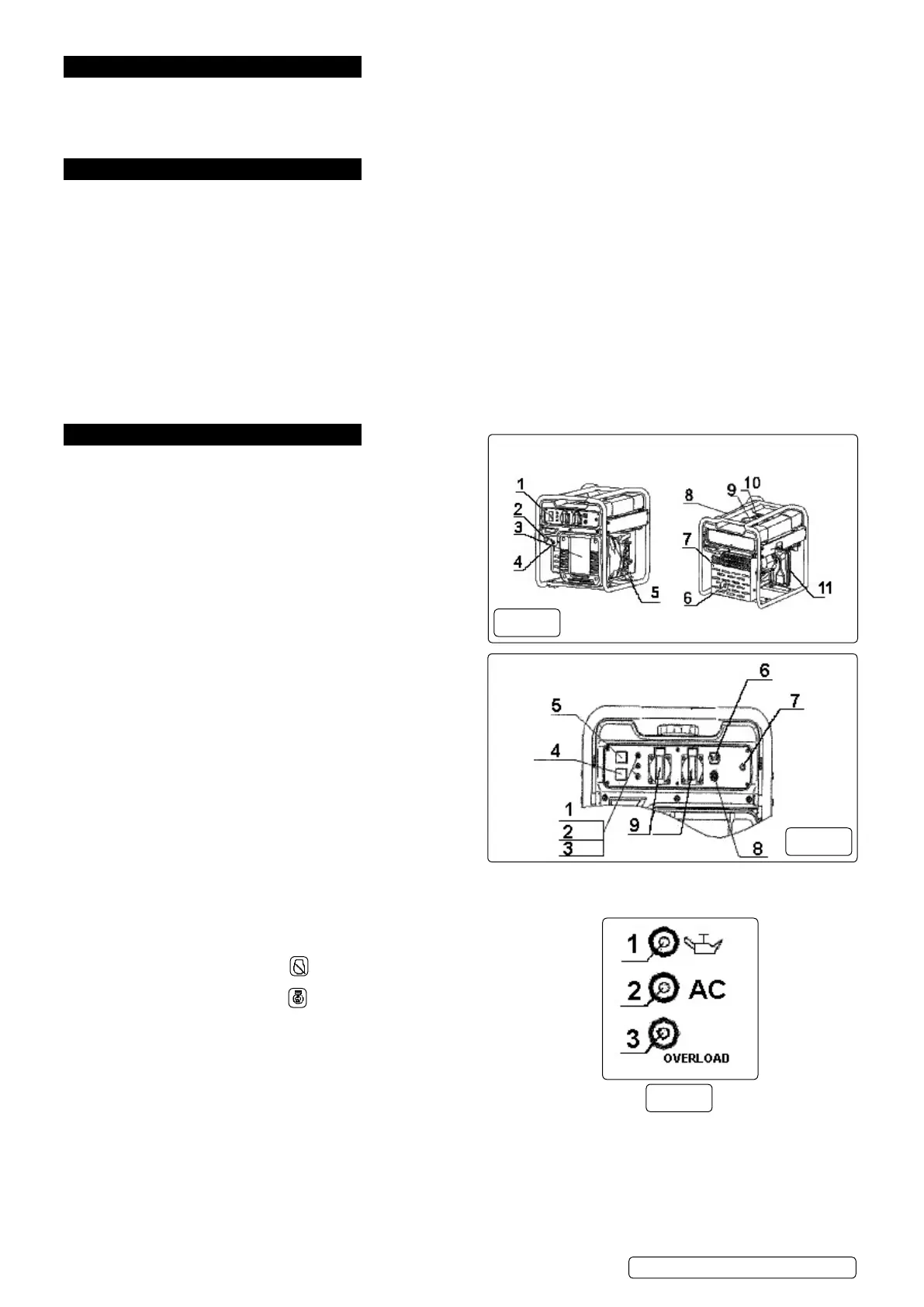
4. OPERATION
4.1. Descriptiong.1.
1. Control panel
2. Choke Knob
3.Inverter cover
4.Fuelcockknob
5. Recoil starter
6.Mufer
7.Mufercover
8.Fueltank
9.Fueltankcap
10. Fuel gauge
11.Airlter
4.2. Control Panel g.2.
1. Oil warning light
2. AC pilot light
3. Overload indicator light
4.Economycontrolswitch
5. Engine switch
6. DC socket
7. Earth terminal
8.DCprotector
9.ACsocket
4.3. Control Functions
4.3.1. Engine Switch
Ignition circuit is switched off
Ignition circuit is switched on
4.3.2. Oil warning light (yellow)
Whentheoillevelfallsbelowthelowerlevel,theoilwarninglightg.3.1.comeson
theenginethenstopsautomatically.Untiltheoilisrelledtheenginewillnotstart.
If the engine stalls or does not start, turn the engine switch to “ON” and then pull
recoilstartercord.Iftheoilwarninglightickersforafewseconds,thereis
insufcientoil.topupoilandrestart.
4.3.3. Overload indicator light (red)
The overload indicator light (3) comes on when an overload is detected, the inverter control unit overheats, or the AC output
voltages rise. The AC protector will trip and stop power generation in order to protect the generator. The AC pilot light (Green) will
go off and the overload indicator light (red) will stay on, The power generation will stop. When this happens proceed as follows.
Turn off any connected electric devices and stop the engine.
Reduce the total wattage of connected appliance into the rated output.
Check for blockages in the cooling air inlet and around the control unit. If any blockages are found, remove.
Afterchecking,restarttheengine.Note:Theoverloadindicatorlightmaycomeonforafewsecondsatrstwhenusingelectrical
g.1
g.2
g.3
GI2300,GI3500Issue2(g1)19/04/18
Original Language Version
© Jack Sealey Limited
 Loading...