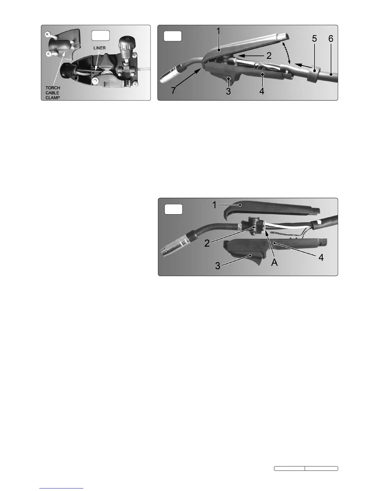
9.6. Replacing wire liner:
9.6.1 A worn or damaged wire liner will seriously affect the performance of the welder and should be immediately replaced. First wind the wire back onto the
spool and secure it. Remove the four screws securing the torch cable clamp to the wire feed unit (fig.14) and take off the clamp.
9.6.2 To open the torch case first take hold of the locking ring (fig.15-5) and turn it anticlockwise until it stops and then pull it off the two halves of the torch case
and slide it a little way down the torch cable.
9.6.3 Lift up the back of the upper torch moulding as shown in fig15-1 and unhook it from the front of the lower moulding (see 7 in fig.15) and lift it off.
9.6.4 Move the lower moulding away from the inner torch assembly as shown in fig16-4.
9.6.5 Disconnect the black liner from the torch control assembly by pressing the locking ring into the connector and withdrawing the liner. See A in fig.14.
9.6.6 With the torch cable as straight as possible pull the liner from the torch cable.
9.6.7 Insert the new liner into the torch cable and secure it in the wire drive unit by replacing the torch cable clamp. See fig.14. Insert the other end of the liner
through the locking ring and fully into the torch control assembly.
9.6.8 Ensure that the switch moulding (fig.16-3) is fully seated down into the lower moulding (4). Place the torch head assembly (2) down into the lower moulding
and arrange the inner connections within the moulding. The gas pipe and wire liner will rest into notches on the inner ribs of the moulding. The two thin
switch wires should be to the left of the gas pipe and the larger black control cable should be to the right of the wire liner.
9.6.9 Hook the upper moulding (1) onto the lower moulding (4) as shown in fig.15-7. Close the upper moulding down onto the lower moulding ensuring that there
are no wires trapped between the two halves. The two mouldings should close easily, do not force them shut.
9.6.10 Once the mouldings are closed slide the locking ring (fig.15-5) up onto them. Turn the locking ring clockwise to secure the assembly.
fig.16
fig.15
fig.14
Original Language Version
MIGHTYMIG150 Issue: 2 - 26/02/10
 Loading...