EasyManua.ls Logo

Sealey MM19.V3 - User Manual

Sealey MM19.V3
4 pages
Print Icon
To Next Page IconTo Next Page
Loading...
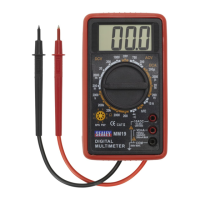
7-FUNCTION MULTIMETER
MODEL NO: MM19.V3
Thank you for purchasing a Sealey product. Manufactured to a high standard, this product will, if used according to these instructions,
and properly maintained, give you years of trouble free performance.
IMPORTANT: PLEASE READ THESE INSTRUCTIONS CAREFULLY. NOTE THE SAFE OPERATIONAL REQUIREMENTS, WARNINGS & CAUTIONS. USE
THE PRODUCT CORRECTLY AND WITH CARE FOR THE PURPOSE FOR WHICH IT IS INTENDED. FAILURE TO DO SO MAY CAUSE DAMAGE AND/OR
PERSONAL INJURY AND WILL INVALIDATE THE WARRANTY. KEEP THESE INSTRUCTIONS SAFE FOR FUTURE USE.
1. SAFETY
When using this multimeter, please observe all normal safety rules concerning:
9 Protection against the dangers of electrical current.
9 Protection of the meter against misuse.
9 Full compliance with safety standards can only be guaranteed if used with the test leads supplied. If necessary, they must be replaced
with genuine Sealey leads with the same electrical ratings. Failure to do so will invalidate the warranty.
8 DO NOT use leads if damaged or if the wires are bared in any way.
1.1. GENERAL SAFETY INSTRUCTIONS
9 Familiarise yourself with the application and limitations of the multimeter as well as the potential hazards.
IF IN ANY DOUBT CONSULT A QUALIFIED ELECTRICIAN. USE EXTREME CAUTION when working with high voltages.
9 When the meter is connected to a circuit, do not touch unused meter terminals.
9 When the magnitude of the value to be measured is unknown, set the range selector to the highest value available.
9 Before commencing testing, follow instructions below and select the correct input sockets, function and range on the multimeter.
9 Before rotating the rotary switch to change functions, disconnect the test leads from the circuit under test.
9 Take care when working with voltages above 35V DC or 25V AC rms. These voltages are considered a shock hazard. Keep fingers
behind the probe barriers whilst measuring.
8 DO NOT test voltages above 750V AC - 1000V DC - the circuitry of the multimeter may be destroyed.
WARNING! NEVER connect the multimeter to a voltage source / live circuit when the rotary switch is set to any other function apart from
Voltage testing.
WARNING! NEVER perform resistance, transistor, diode or continuity measurements on live circuits.
9 ALWAYS discharge lter capacitors in power supplies and disconnect the power when making resistance or diode tests.
WARNING! Voltage checks on electrical outlets can be difcult and misleading because of the uncertainty of connection to the
recessed electrical contacts. Other means should be used to ensure that the terminals are not “live”.
8 DO NOT use the multimeter in a potentially explosive atmosphere.
8 NEVER operate the meter unless the back cover and the battery and fuse doors are in place and fastened securely.
9 If any abnormal readings are observed, the multimeter must be checked out by an authorised technician.
9 When not in use, store the multimeter carefully in a safe, dry, childproof location out of direct sunlight.
9 Storage temperature range -20°C to 60°C.
9 ALWAYS turn off the power and disconnect the test leads before opening the doors to replace the fuse or batteries.
9 The user shall ensure that test probes are correctly selected in order to prevent danger. Probes shall be selected to ensure
that adequate barriers guard against inadvertent hand contact with live conductors under test and that probes have minimal
exposed probe tips. Where there is a risk of the probe tip short circuiting with other live conductors under test, it is recommended that
the exposed tip length shall not exceed 4mm.
The warnings, cautions and instructions referred to in this manual cannot cover all possible conditions and situations that
may occur. It must be understood that common sense and caution are factors which cannot be built into this product, but must
be applied by the operator.
1.2. SAFETY SYMBOLS
This symbol adjacent to another symbol, terminal or operating device indicates that the operator must refer
to an explanation in the Operating Instructions to avoid personal injury or damage to the meter.
This WARNING symbol indicates a potentially hazardous situation, which if not avoided, could result in death or serious
or serious injury.
This CAUTION symbol indicates a potentially hazardous situation, which if not avoided, may result damage to the product.
This symbol, adjacent to one or more terminals identies them as being associated with ranges that may, in normal use, be
subjected to particularly hazardous voltages. For maximum safety, the meter and its test leads should not be handled when
these terminals are energized.
This symbol indicates that a device is protected throughout by double insulation or reinforced insulation.
WARNING
CAUTION
Refer to
instruction
manual
MM19.V3 Issue:6 (H,F) 21/10/21
Original Language Version
© Jack Sealey Limited
Question and Answer IconNeed help?

Do you have a question about the Sealey MM19.V3 and is the answer not in the manual?

Overview

The Sealey MM19.V3 is a 7-Function Multimeter designed for general-purpose electrical measurements. It features a large (46 x 25mm), clear, and easy-to-read LCD display and is supplied with test leads.

Function Description:

The multimeter can measure a variety of electrical parameters, including:

  • AC Voltage: Measures alternating current voltage.
  • DC Voltage: Measures direct current voltage.
  • DC Current: Measures direct current.
  • Resistance: Measures electrical resistance.
  • Audible Continuity: Provides an audible indication for circuit continuity (sounds if resistance is less than 100Ω).
  • Diode Verification Mode: Tests diodes.
  • Transistor Verification Mode (hFE Test): Measures the DC current gain (hFE) of transistors.

Important Technical Specifications:

  • Model No.: MM19.V3
  • AC Voltage (Accuracy): 200V, 750V (±2% reading + 2 digits (50/60Hz)). Overload protection: 1000 V DC or 750Vrms AC for all ranges. Response: Average responding, calibrated in rms of a sine wave. Frequency range: 45Hz - 450Hz.
  • DC Voltage (Accuracy):
    • 200mV: ±(1.5% reading + 2 digits)
    • 2000mV, 20V, 200V: ±(1.5% reading + 2 digits)
    • 1000V: ±(1.8% reading + 2 digits)
    • Overload protection: 220Vrms AC for 200mV range and 1000VDC or 750Vrms AC for other ranges.
  • AC Current (Accuracy): Not specified (indicated as "No").
  • DC Current (Accuracy):
    • 200μA, 2000μA, 20mA: ±(2.0% reading + 2 digits)
    • 200mA: ±(2.2% reading + 2 digits)
    • 10A: ±(2.0% reading + 2 digits)
    • Overload protection: 200mA/250V fuse (10A range unfused). Measuring voltage drop: 200mV.
  • Resistance (Accuracy):
    • 200Ω: ±(1.8% reading + 5 digits)
    • 2000Ω, 20KΩ, 200kΩ: ±(1.8% reading + 2 digits)
    • 2000kΩ: ±(2% reading + 2 digits)
    • Maximum open circuit voltage: 2.8V. Overload protection: 15 seconds maximum 220Vrms on all ranges.
  • Capacitance (Accuracy): Not specified (indicated as "No").
  • Temperature (Accuracy): Not specified (indicated as "No").
  • Frequency (Accuracy): Not specified (indicated as "No").
  • Duty Cycle: Not specified (indicated as "No").
  • Continuity Audible: Yes. Overload protection: 15 seconds maximum 220Vrms.
  • Transistor hFE Data Test: Range 0-1000. Basic current is approx. 10μA, Vce is approx. 3V. Overload protection: 10 seconds max. 220Vrms.

Usage Features:

  • Safety First: Always observe normal safety rules concerning protection against electrical current and meter misuse. Use only genuine Sealey test leads.
  • High Voltage Caution: Exercise extreme caution when working with high voltages (above 35V DC or 25V AC rms). Keep fingers behind probe barriers. Do not test voltages above 750V AC - 1000V DC.
  • Function Switch: Before rotating the rotary switch to change functions, disconnect the test leads from the circuit under test.
  • Range Selection: When the magnitude of the value to be measured is unknown, set the range selector to the highest value available.
  • DC Voltage Measurement: Set the function switch to the highest VDC position. Insert the black test lead into the negative (COM) jack and the red test lead into the positive (V) jack. Touch the probes to the respective sides of the circuit. Read the voltage and adjust the range for higher resolution.
  • AC Voltage Measurement: Set the function switch to the highest VAC position. Insert the black test lead into the negative (COM) jack and the red test lead into the positive (V) jack. Touch the probes to the respective sides of the circuit. Read the voltage and adjust the range for higher resolution. Be aware that probe tips may not be long enough to contact recessed live parts in some 240V outlets.
  • DC Current Measurement: For measurements up to 200mA DC, set the function switch to the highest DC mA position and insert the red test lead into the (mA) jack. For measurements up to 10A DC, set the function switch to the 10A range and insert the red test lead into the (10A) jack. Disconnect power, open the circuit, connect leads in series, then reapply power. Do not make current measurements on the 10A scale for longer than 30 seconds.
  • Resistance Measurement: Disconnect power to the unit under test and discharge capacitors before measuring. Set the function switch to the highest Ω position. Insert the black test lead into the negative (COM) jack and the red test lead into the positive Ω jack. Touch probes across the circuit or component. Disconnect one side of the component for accurate readings. Adjust the range for higher resolution.
  • General Operation: Do not apply voltage or current exceeding specified maximums. Do not operate the meter in a potentially explosive atmosphere. Always turn the function switch to "OFF" when not in use.

Maintenance Features:

  • Battery Installation: To install batteries, disconnect test leads, loosen the two cover screws, open the battery cover, insert the battery with correct polarity, and replace the cover. Do not operate the meter until the battery cover is securely fastened.
  • Fuse Replacement: The fuse and battery compartment are at the rear of the unit. Always turn off power and disconnect test leads before opening the doors to replace the fuse or batteries.
  • Storage: When not in use, store the multimeter carefully in a safe, dry, childproof location out of direct sunlight. Storage temperature range: -20°C to 60°C.
  • Troubleshooting: If the meter does not work properly, check the fuses and battery. If abnormal readings are observed, the multimeter must be checked by an authorised technician.
  • Environmental Protection: Dispose of the product at the end of its working life in compliance with EU WEEE Directive. Recycle unwanted materials, packaging, and fluids (if applicable) according to local regulations.

Sealey MM19.V3 Specifications

General IconGeneral
BrandSealey
ModelMM19.V3
CategoryMeasuring Instruments
LanguageEnglish

Related product manuals